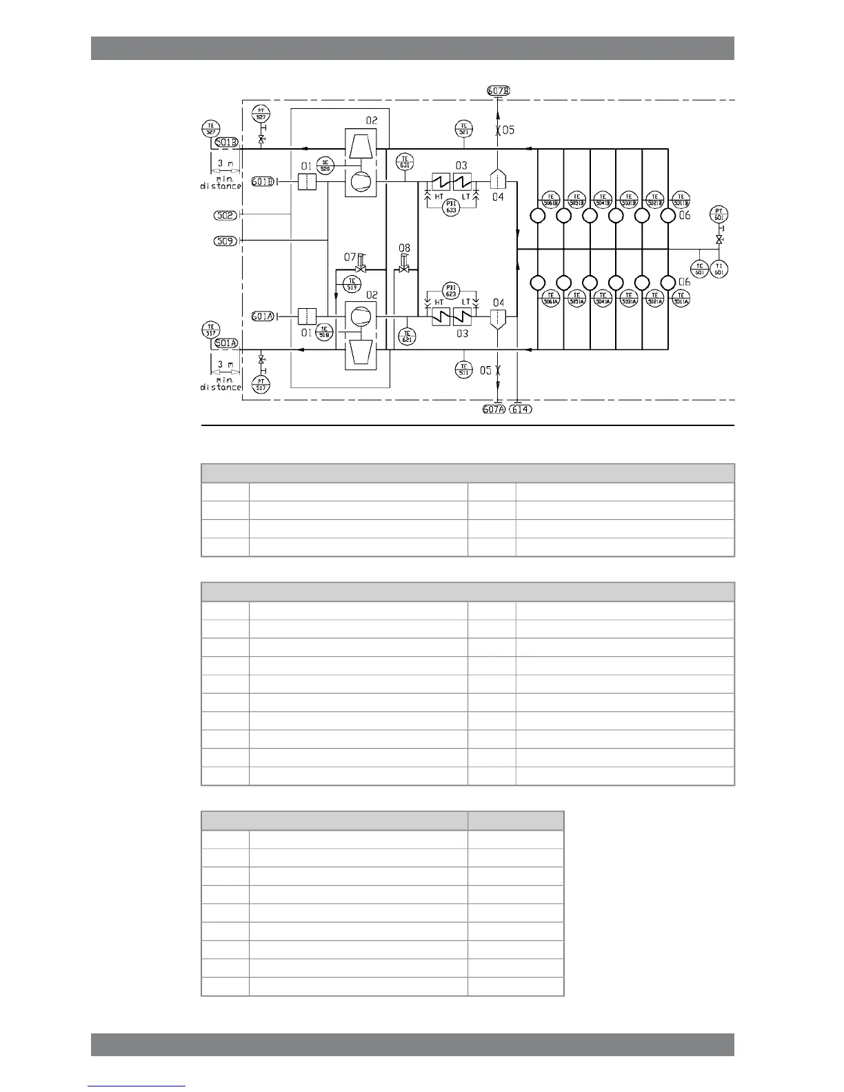
Fig 11-2 Charge air and exhaust gas system, V-engines (DAAE077307C)
System components
Restrictor05Air filter01
Cylinder06Turbocharger02
Exhaust gas wastegate valve07Charge air cooler03
Charge air by-pass valve08Water separator04
Sensors and indicators
Exhaust gas temperature, cylinder 0xBTE50x1BExhaust gas temperature, TC A inletTE511
Charge air pressure, engine inletPT601Exhaust gas pressure, TC A outletPT517
Charge air temperature, engine inletTE601Exhaust gas temperature, TC A outletTE517
Charge air temperature, engine inletTI601Turbocharger A speedSE518
Charge air temperature, CAC inlet, A-bankTE621Exhaust gas temperature, wastegate outletTE519
CAC pressure difference, A-bankPDI623Exhaust gas temperature, TC B inletTE521
Charge air temperature, CAC inlet, B-bankTE631Exhaust gas pressure, TC B outletPT527
CAC pressure difference, B-bankPDI633Exhaust gas temperature, TC B outletTE527
x = cylinder numberTurbocharger B speedSE528
Exhaust gas temperature, cylinder 0xATE50x1A
SizePipe connections
DN600Exhaust gas outlet, A-bank501A
DN600Exhaust gas outlet, B-bank501B
DN32Cleaning water to turbine502
OD18Cleaning water to compressor509
Air inlet to turbocharger, A-bank601A
Air inlet to turbocharger, B-bank601B
OD22Condensate after air cooler, A-bank607A
OD22Condensate after air cooler, B-bank607B
OD18Scavenging air outlet to TC cleaning valve unit614
11-2 Wärtsilä 46F Product Guide - a19 - 1 December 2017
Wärtsilä 46F Product Guide11. Exhaust Gas System

 Loading...


