5)SwitchontheWAT-902H,monitorandallotheralliedequipment.
NOTE: Whenthepicturedosenotappearonthemonitorscreen,switchoffallequipmentandcheckthatall
connectionstoalltheappliancesarecorrect.
6)Focusing
FocusingthelensoftheWAT-902Hisachievedwhilelookingatthemonitorscreen.
NOTE: Incaseswhentheunitcannotbefocusedmanually,usethefocusingadjustmentmethodsetoutbelow.
7)SelectanyrequiredshutterspeedbychangingSHUTTER⑦.
IMPORTANT NOTES ON FOCUSING
: Attach the required lens on the WAT-902H and loosen the hexagonal screws③. (3pcs.)
Be extremely careful not to drop the lens.
: Set the focus ring to the infinitive (∞) position, and while looking at the monitor screen, move the lens forwards or
backwards to focus.
: Tighten the hexagonal focusing adjustment screws③ (3pcs.) when focusing is completed.
IMPORTANT NOTES FOR USAGE OF AUTO IRIS LENS
: An optimal picture may not be obtained on the monitor screen due to the different kinds of lenses used which give
different angular views and different contrasts of objects. In this case adjustment must be made by reading through as
shown below.
①Check that the required auto iris lens has the adjustment control as shown in the drawing on
the left.
②Set the ALC(Automatic Level Control) adjustment control in the center between AV and PK
on the lens using a small screw driver.
③Point the lens towards the object while looking at the screen.
Turn the LEVEL adjustment control clockwise or anti-clockwise to obtain the optimal
brightness of an object on the monitor screen.
④Turn the ALC adjustment control towards PK when the contrast of the object needs to be stronger or towards AV when
it needs to be weaker.
⑤Continually repeat the procedures ③ and ④ to obtain an optimal picture.
EXAMPLE FOR SHUTTER SWITCH USE
ON: When a fixed lens without auto iris function is used.
When brightness of an object is continually variable such as continuous monitoring of the
outdoors through a 24 hour cycle.
OFF: When an auto iris lens is used.
When an optimal picture can be obtained on the monitor screen in conditions that light is less
variable such as indoors.
FL: When a flickering phenomenon on the monitor screen is caused by a source such as
fluourescent or mercury lighting.
NOTE: Select the most appropriate function out of the above three that correspond to your required monitoring.
: Smear phenomenon (a portion of an object with high brightness projecting bright trails up and down) appear
on the monitor screen, when an object with high brightness is monitored. (especially in the ON position) This dose
not mean the camera is damaged. This is normal.
8)AGCLo/Hi⑨ switch
Itisrecommendedtosetthe⑨ switchtotheHi(uponshipment)position,whentheWAT-902Hisusedindark
environmentsorthrougha24hourcycle.
The⑨ switchmustbesettotheLoposition,whenimprovementofS/N(Signal/Noiselevel)isrequired.Inthiscase,
theAGCrangecorrespondstothelenssetatthreestopssmaller.
9)BackLightCompensation
BackLightCompensationontheWAT-902Hisinnormaloperationasastandardfunction.
ThefunctioniswhattheareameasuringthelightintensityofthefieldofviewintheWAT-902Hisrestricted,when
anauto-irislensisusedortheSHUTTER⑦ switchisON.
Inthefieldofviewwhichcorrespondstothemonitorscreen,whenanobjectbrighterinilluminationsuchassunor
brightilluminationisplacedexceedingtheslantareainthefieldofview,theauto-irislenscanselectthebrightness
oftheslantareainthefieldofviewinprioritytothelightintensityofthebrighterobjectexceededintheslantareain
thefieldofview.
The same operation as the above is carried out at the ON position of the SHUTTER ⑦
switch even when an iris-fixed lens.
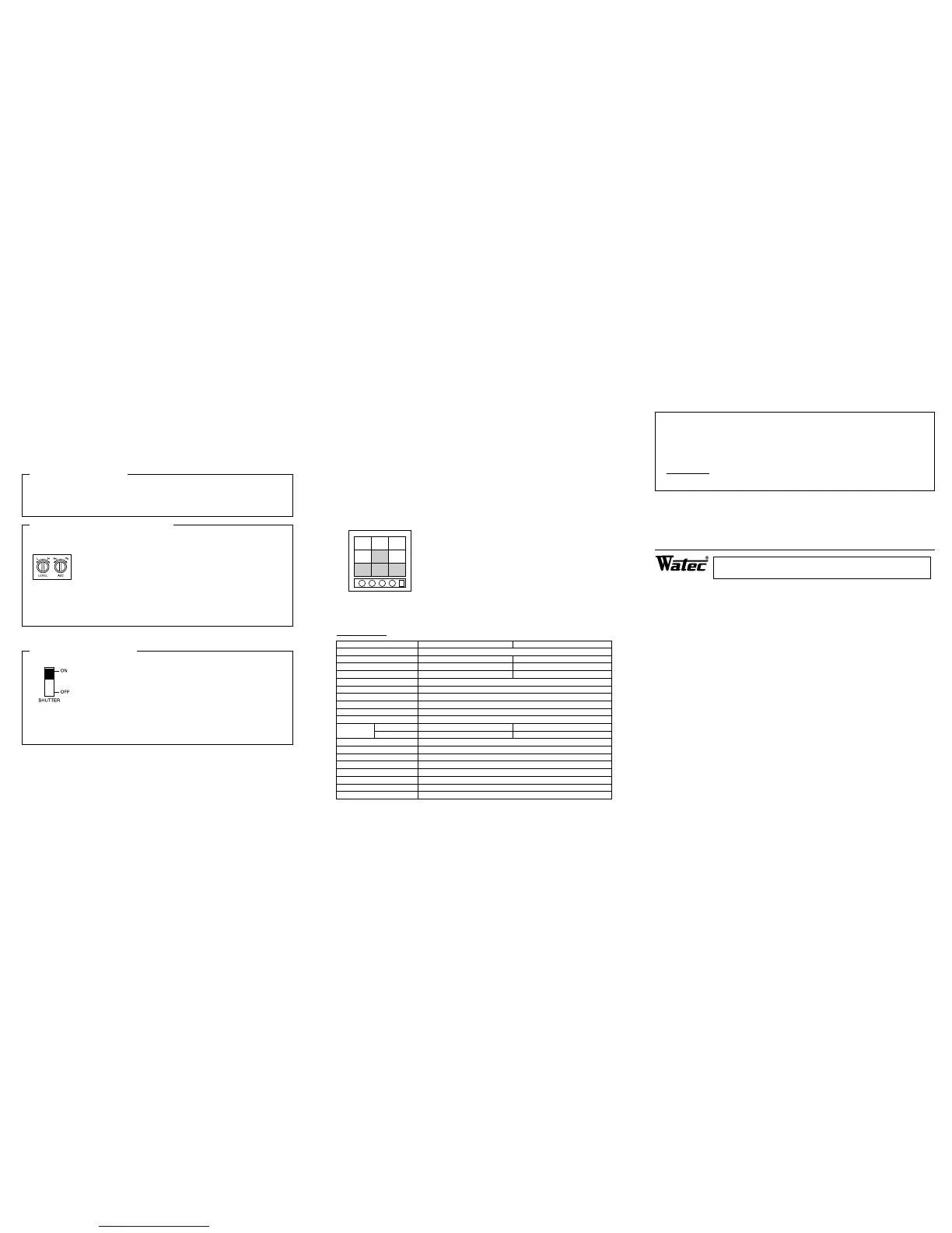
The left drawing shows the area where the light intensity can be measured by the Back
Light Compensation function in the field of view. Namely the area indicated by the middle
square and lower 3 squares in the drawing on the left applies the area operative by the
Back Light Compensation function.
SPECIFICATIONS:
Model
Pick-up element
Number of total pixels
Number of effective pixels
Unit cell size
Sync system
Scanning system
Video output
Resolution
Minimum illumination
S/N ratio
Shutter ON(EI)
OFF
AGC
Gamma characteristic
Back light compensation
Power supply
Current
Storage temperature
Operating temperature
Weight
WAT-902H (EIA) WAT-902H (CCIR)
1/2" Interline transfer CCD image sensor
811(H)×508(V) 795(H)×596(V)
768(H)×494(V) 752(H)×582(V)
8.4μm (H)×9.8μm (V) 8.6μm (H)×8.3μm (V)
Internal
2:1 Interlace
1Vp-p 75Ω (Unbalanced)
570TV Lines
0.0003 Lux F1.4 (AGC Hi) 0.002 Lux F1.4 (AGC Lo)
46dB (AGC off)
1/60~1/100000 sec. 1/50~1/100000 sec.
1/60 sec. 1/50 sec.
AGC Hi : 5~50dB, AGC Lo : 5~32dB
Γ≒0.45
ON
DC +12V±10%
160mA
−30℃〜+70℃
−10℃〜+40℃
Approx. 90g
This device complies with Part 15 of the FCC Rules.
Operation is subject to the following two conditions:
(1)This device may not cause harmful interference,and
(2)this device must accept any interference received,including interference that may cause undesired
operation.
Important:
The camera mentioned above does not comply with this regulation, if it is modified at your disposal.
Design and specifications are subject to change without notice.
WATEC is not responsible for any inconvenience or the attendant damages to the video, audio and monitoring recording
equipment,
caused by misuse, misoperation or inproper wiring of our equipment.
If for any reason the WAT-902H does not work properly, or if you have any questions regarding installation or operation,
please contact the distributor or dealer from which it was purchased.
Address : 254-2, Nihonkoku, Daihoji, Tsuruoka-Shi, Yamagata-Ken, 997-0017 JAPAN.
Phone : +81-235-23-4400 Fax : +81-235-23-4409
http://www.watec.net E-mail : info@watec.net
Watec Co.,Ltd.
 Loading...