28
SPECIFICATIONS
Depth
Width
e
th
Hei
h
Wi
t
Impression Series
®
Specifications
Please use “IMP” as prefix when specifying Impression Plus Series
water softeners.
Manufactured by Water-Right, Inc. • 1900 Prospect Court • Appleton, WI 54914 • 800-777-1426 • water-right.com
SPE-IM/IMP SOFT RevA0318
CYCLE TIMES AND USAGE
IM Model
IMC Model
1
All Impression water softeners are set at medium salting.
2
Iron removal may vary depending on form of iron, pH and other local conditions. On waters
that are pre-chlorinated or where other pre-oxidation occurs, an iron precipitate can form that
is too small to be filtered.
3
Unit not tested for capacity at these flow rates. Water quality may vary.
MODEL
IM-844
IMP-844
IM-1044
IMP-1044
IM-1054
IMP-1054
IM-1354
IMP-1354
IMC-835
IMPC-835
IMC-1035
IMPC-1035
1
Capacity:
(Grains/Lbs. NaCI)
Minimum
15,600 @ 3.0 23,600 @ 6.0 35,400 @ 9.0 53,000 @ 12.0 13,600 @ 3.0 23,600 @ 6.0
Medium
21,600 @ 6.0 28,400 @ 9.0 44,400 @ 15.0 64,200 @ 18.0 18,000 @ 6.0 28,400 @ 9.0
Maximum
25,600 @ 9.0 32,000 @ 15.0 48,800 @ 21.0 72,800 @ 24.0 21,000@ 9.0 32,000 @ 15.0
Amount of Media (Cu. Ft.)
.75 1.0 1.5 2.5 0.5 1.0
Maximum Water Hardness (GPG)
50 75 100 100 50 75
2
Maximum Iron (PPM)
1.0 1.0 1.0 1.0 1.0 1.0
3
Peak Flow Rate (GPM @ P-PSI)
11.4 @ 15.0 17.1 @ 15.0 14.3 @ 15.0 18.5 @ 15.0 12.2 @ 15.0 17.1 @ 15.0
Continuous Flow Rate (GPM @ P-PSI)
5.0 @ 5.4 5.0 @ 2.8 5.0 @ 3.8 5.0 @ 2.4 5.8 @ 5.0 5.0 @ 2.8
Water Pressure Range (PSI)
25-100 25-100 25-100 25-100 25-100 25-100
Water Temp. (ºF)
33-100 33-100 33-100 33-100 33-100 33-100
Electrical Requirements (volts-hertz) 110-50/60 110-50/60 110-50/60 110-50/60 110-50/60 110-50/60
Pipe Size 1” 1” 1” 1” 1” 1”
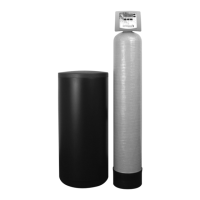
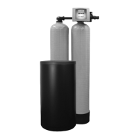
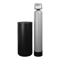
Total Dimensions:
Media Tank and Valve 8”W x 52”H 10”W x 52”H 10”W x 62”H 13”W x 62”H 14”W x 44.5”H 14”W x 44.5”H
Brine Tank 18”W x 33”H 18”W x 33”H 18”W x 33”H 18”W x 40”H N/A N/A
Depth N/A N/A N/A N/A 20.5” 20.5”
MODEL
IMRC-1054
IMPRC-1054
IMRC-1354
IMPRC-1354
1
Capacity:
(Grains/Lbs. NaCI)
Minimum
23,600 @ 6.0 35,400 @ 9.0
Medium
28,400 @ 9.0 44,400 @ 15.0
Maximum
32,000 @ 15.0 48,800 @ 21.0
Amount of Resin Media (Cu. Ft.)
1.0 1.5
Amount of Carbon Media (Cu. Ft.)
.5 1.0
Maximum Water Hardness (GPG)
75 100
2
Maximum Iron (PPM)
1.0 1.0
3
Peak Flow Rate (GPM @ P-PSI)
15.6 @ 15.0 20.4 @ 15.0
Continuous Flow Rate (GPM @ P-PSI)
9.7 @ 7.5 13.2 @ 7.5
Water Pressure Range (PSI)
25-100 25-100
Water Temp. (ºF)
33-100 33-100
Electrical Requirements (volts-hertz) 110-50/60 110-50/60
Pipe Size 1” 1”
Total Dimensions:
Media Tank and Valve 10”W x 62”H 13”W x 62”H
Brine Tank 18”W x 33”H 18”W x 40”H
MODEL
IM-844
IMP-844
IM-1044
IMP-1044
IM-1054
IMP-1054
IM-1354
IMP-1354
IMC-835
IMPC-835
IMC-1035
IMPC-1035
MIN. GAL. MIN. GAL. MIN. GAL. MIN. GAL. MIN. GAL. MIN. GAL.
Brine Refill
4 2 6 3 10 5 12 6 4 2 6 3
The above sequence takes place prior to regeneration; therefore minutes are not included in totals
Backwash
6 10 8 22 8 22 10 32 6 10 8 22
Brine & Rinse
40 16 60 24 90 36 90 47 40 16 60 24
Rapid Rinse
4 7 4 11 4 11 4 13 4 7 4 11
Total 50 33 72 57 102 69 104 92 50 33 72 57
IM/IMC SPECIFICATIONS
IMRC SPECIFICATIONS

 Loading...