EasyManua.ls Logo

Watlow F4T User Manual

Watlow F4T
331 pages
To Next Page IconTo Next Page
To Previous Page IconTo Previous Page
Page #201 background imageLoading...
Page #201 background image
Watlow F4T 198 Chapter 5 Function Reference
Retentive: measures how long the input is active and triggers the output when the cumulative
time reaches a specified duration
Off
When the Timer blocks function is set to Off, the transmitter is in its inactive state. See
Transmitter Active Level.
Signals
Direction Label Type Function
Transmitter - - - - Digital
In the state selected with the Transmitter Active Level pa-
rameter
Function
To disable the timer and hold the output is in its inactive state, set Function to Off.
Transmitter Active Level
Choose the outputs active state. When Function is set to Off, the output is in the inactive
state, the opposite of the state selected here.
Options:
High: the timer’s output is off while the timer is disabled.
Low: the timer’s output is on while the timer is disabled.
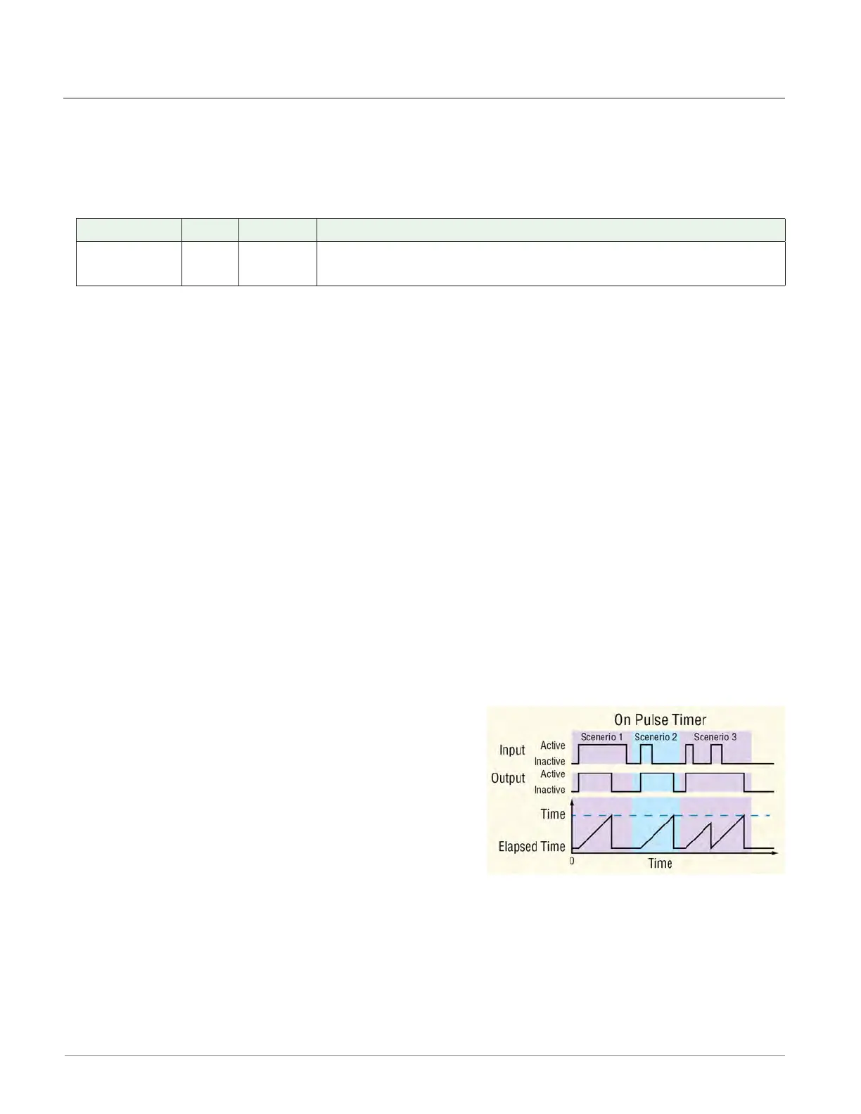
On Pulse
This function produces an output pulse of a constant duration. This can be used as a mini-
mum on time for devices that do not tolerate excessive cycling.
To understand the timers behavior, consider these scenarios illustrated in the timing diagram
below:
1. When input changes to its active state, the function sets the output to its active state and
begins accumulating the elapsed time. Once the elapsed time reaches the value set for
the Time parameter, the output returns to its in-
active state and the elapsed time resets to zero.
2. The input need not stay active for the output to
remain active for the specified time.
3. However, while the timer is running, if the input
becomes inactive and then active again, the pulse
length is increased.
Note:
The active and inactive states are user configurable with the parameters described below.
Therefore, the description of the timer’s behavior for its inputs and outputs refers to the
active and inactive states for each rather than on or off. For example, if the input’s ac-
tive state is set to High, the timer starts running (becomes active) when the input changes
from low (off) to high (on). However, if the input’s active state is set to Low, the timer
starts running (becomes active) when the input changes from high (on) to low (off).

Table of Contents

Other manuals for Watlow F4T

Questions and Answers:

Watlow F4T Specifications

General IconGeneral
InputsThermocouple, RTD, mA, V
OutputsRelay, SSR, mA, V
CommunicationEthernet, Modbus RTU
Data LoggingYes
CertificationsCE, UL, cUL, RoHS
Control ModesPID, On/Off
Power Supply100 to 240 VAC
Operating Temperature0 to 50°C
Enclosure RatingIP65
Display4.3 in. (109 mm) color touch panel LCD
Control LoopsUp to 4

Summary

Chapter 1: Overview

Available F4T Literature and Resources

Lists available documentation and resources for the F4T controller.

Technical Assistance

Provides contact information and steps for obtaining technical support.

Document Overview and Purpose

Explains the scope and purpose of the F4T User's Guide.

A Conceptual View of the F4T System

Provides a high-level overview of the F4T controller's architecture and functionality.

Chapter 2: Composer® Software

Installing Composer® Software

Step-by-step guide for installing the Composer software on a PC.

Using Composer® Software

Instructions on connecting to the controller and navigating Composer's interface.

Configuring Pluggable Flex Modules

Details on how to configure and manage Flex Modules installed in the controller.

Creating and Editing Profiles Using Composer®

Guide to creating, editing, and managing profiles for the F4T controller.

Chapter 3: Using the F4T Front Panel

Navigating and Understanding the User Interface (UI)

Explains the structure and navigation of the F4T's front panel menus.

Home Screen Described

Details the components and layout of the F4T's configurable home screen.

Data Logging

Instructions for setting up and initiating data logging on the F4T controller.

Chapter 4: Application Examples

Single Loop Control

Demonstrates a basic single loop control configuration using the F4T controller.

Heat and Cool Control Loop

Explains a heat and cool control loop application example.

Cascade Control

Details how to configure and use cascade control for improved process management.

Compressor Control

Explains how to coordinate compressor demands for cooling/dehumidification.

Chapter 5: Function Block Reference

F4T Functions Described

Overview of function blocks, signals, and error status within the F4T system.

Alarm

Explains how to use the alarm block to monitor signals and trigger outputs.

Control Loop

Details how to use control loop blocks for temperature or other process value manipulation.

Math

Describes various mathematical operations available for signal processing.

Chapter 6: Appendix

Communications

Information on communication protocols like Modbus TCP and SCPI.

F4T Base Ordering Information

Provides details on how to order F4T base units and their configurations.

Flex Modules and Limit I/O Specifications

Technical specifications for Flex Modules, including I/O capabilities and limits.

Declaration of Conformity

Lists the product's compliance with various electrical and safety directives.

Related product manuals