Do you have a question about the Watt Drive V2500 Series and is the answer not in the manual?
Manual provides guidance on installation, parameter setting, troubleshooting, and maintenance.
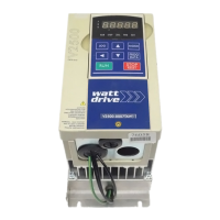
Details on the inverter's nameplate, including model, input/output specifications, and serial number.
Explains the components of the V2500 model number, including series, voltage, and power.
Explains the different parts of the series number, indicating production details.
Guidelines for proper storage conditions, including temperature, humidity, and pressure.
Precautions for mounting location, heat dissipation, and general installation guidelines.
General guidelines for compliance with CE standards, NEC, CEC, and UL/cUL requirements.
Specifies ambient conditions like temperature, humidity, vibrations, and location for optimal inverter performance.
Outlines power supply requirements and conditions for V2500 inverter operation.
Details requirements for shielded wiring for motor and control lines, and separation of circuits.
Mentions using specific filters and following installation notes for EMC compliance.
Illustrates the circuit diagram for connecting the V2500 series inverter to motors and control components.
Explains the function of each terminal on the AC drive, categorizing power and control terminals.
Details the functions and factory settings of various control terminals for input and output signals.
Provides diagrams and specifications for the main circuit wiring of V2500 AC drives for specific power ranges.
Crucial notes and precautions for AC drive wiring, including grounding, lead routing, and protection devices.
Precautions for operating motors with the AC drive, especially regarding standard motors at low speeds.
Details the controls, indicators, and display messages of the digital keypad for V2500 drive.
Illustrates step-by-step procedures for navigating modes, setting parameters, and modifying data using the digital keypad.
Lists and explains user-configurable parameters, including control methods and basic settings.
Details fundamental parameters like maximum output frequency, voltage, and acceleration/deceleration times.
Covers parameters related to how the drive receives commands and operates, such as frequency source selection.
Defines parameters for output functions, including multi-function outputs and analog/digital signal configurations.
Explains parameters related to input functions, such as analog input bias, polarity, gain, and multi-function inputs.
Lists parameters for multi-step speed control and Programmable Logic Controller (PLC) functions.
Details protection parameters for the inverter, such as over-voltage, over-current, and overload settings.
Covers parameters related to motor characteristics, including rated current, poles, and auto-detection settings.
Outlines parameters for communication settings, such as address, transmission speed, and protocol.
Specifies parameters for PID (Proportional-Integral-Derivative) control, including feedback input, gains, and output limits.
Describes parameters for controlling fan and pump operations, including V/F curve selection and motor start-up/stop frequencies.
Provides basic check-up items for detecting abnormalities during AC drive operation.
Outlines periodic maintenance tasks, including tightening screws, checking for corrosion, and cleaning.
Indicates abnormal increase in current, with corrective actions provided.
Refers to IGBT protection fault, with troubleshooting steps.
Signifies DC bus voltage exceeding its maximum allowable value.
Indicates excessive heat detected by the temperature sensor, with corrective actions.
DC bus voltage has fallen below its minimum value; check input voltage.
Excessive drive output current; check motor overload and torque compensation.
Internal electronic overload trip; check settings and motor capacity.
Motor overload condition; reduce motor load or adjust over-torque settings.
Communication error; check connections and communication protocol.
Over-current during acceleration; check insulation, boost, or capacity.
Over-current during deceleration; check insulation, time, or capacity.
Over-current during steady state operation; check insulation, stall, or capacity.
External fault triggered by EF-GND terminal; output turns off.
Emergency stop triggered by multi-function input terminals.
Internal memory IC cannot be programmed.
Internal memory IC cannot be read.
Drive's internal circuitry is abnormal.
Hardware protection failure.
Software protection failure.
Auto accel/decel failure.
Ground fault detected; check IGBT module and insulation.
External Base Block active; AC drive output turned off.
Analog feedback error; check parameters and wiring.
PG feedback signal error; check system reaction and detection times.
Load current is lower than setting; check parameters or load condition.
Counter cause external fault; check parameters or trigger signal.
Power input phase loss or unbalance; check voltage and terminal tightness.
Lists and explains user-configurable parameters, including control methods and basic settings.
Details fundamental parameters like maximum output frequency, voltage, and acceleration/deceleration times.
Covers parameters related to how the drive receives commands and operates, such as frequency source selection.
Defines parameters for output functions, including multi-function outputs and analog/digital signal configurations.
Explains parameters related to input functions, such as analog input bias, polarity, gain, and multi-function inputs.
Lists parameters for multi-step speed control and Programmable Logic Controller (PLC) functions.
Details protection parameters for the inverter, such as over-voltage, over-current, and overload settings.
Covers parameters related to motor characteristics, including rated current, poles, and auto-detection settings.
Lists special parameters for DC braking, speed search, energy saving, and auto restart functions.
Outlines parameters for communication settings, such as address, transmission speed, and protocol.
Specifies parameters for PID (Proportional-Integral-Derivative) control, including feedback input, gains, and output limits.
Describes parameters for controlling fan and pump operations, including V/F curve selection and motor start-up/stop frequencies.
Recommends circuit breaker ratings for V2500 drives based on input/output current.
Lists recommended line fuse specifications for various V2500 models.
Lists recommended braking resistors and brakechoppers for V2500 AC drives.
Provides a cross-reference table for EMI filters suitable for different V2500 inverter models.
Details the installation of feedback cards for different V2500 series models.
Shows basic wiring diagrams for feedback cards, with and without RPM meters.
Describes the symbols and functions of terminals on the feedback card.
Provides wiring notes for feedback cards, including cable types and routing.
Shows the designations for control terminal blocks on the feedback card.
Illustrates different types of pulse generators and their switch configurations.
| Brand | Watt Drive |
|---|---|
| Model | V2500 Series |
| Category | DC Drives |
| Language | English |