UNIT DESCRIPTION
The Miro Decorator DRD8 Wireless Multilocation Controller is used together
with Miro Decorator wireless devices to control lighting or appliance loads from
multiple locations. The DRD8 can be used in a group with the following Miro
Decorator devices:
DRD2 Wireless Incandescent Dimmer
DRD3 Wireless Switch
DRD4 Wireless Universal Dimmer
DRD9 Wireless Fan Control
MRP6W Wireless Plug-In Lamp Module
MRP7W Wireless Plug-In Appliance Module
Load Types
The DRD8 has no direct connection to the load. See the installation instructions
or specifications for the device connected to the load to determine compatibility
with those devices.
Miro Wireless
Miro wireless devices use radio signals to communicate with each other
to control lighting and other types of electric loads in selected areas. They
use the 900MHz band for high-speed control communication. Using the patented
“frequency-agile” Top Dog™ technology, Miro wireless devices avoid interference
with other 900MHz devices, such as cordless phones and baby monitors.
Application Assistance
The Miro Installation Guide provides more information about configuring scenes
and presets. Instructions for installation and use are included with
the relevant Miro wireless devices. Application support information and the Miro
Installation Guide is available on-line.
INSTALL IN COMPLIANCE WITH ALL APPLICABLE
CODES & STANDARDS.
Failure to follow these instructions may cause
personal injury or equipment damage.
CAUTION
TURN THE POWER OFF AT THE CIRCUIT BREAKER
BEFORE INSTALLING THE CONTROLLER.
GND
LINE
NEUT
SUPPLY
WIRES
SET HOUSE ID
All Miro wireless devices installed in the same home must acquire the same
unique House ID before use. This process is known as house binding. Each Miro
wireless device is bound to all other Miro wireless devices in the house.
New Installation
1. With all devices installed and energized, make sure that every Miro wireless
device LED is yellow. If any LED is off, be sure the circuit breaker is on and the
device is correctly installed.
2. Press
on any device paddle until
the LED flashes yellow (about 2
seconds). This indicates that it has
acquired a unique House ID.
3. Make sure that all other Miro
wireless device LEDs are flashing
green, indicating that they have
acquired the same House ID.
4. Return to the device used in step 2, which is still flashing yellow. Press
until the LED changes to solid green (about 2 seconds). All device LEDs in the
House change to solid green, indicating house binding is complete.
Adding a Device to an Existing Installation
If you’re adding or replacing a device in a Miro wireless installation that is already
operating, the new device must be bound to the same House ID as the other Miro
wireless devices in the house. After the new device is powered up, the LED should
be solid yellow. This indicates that it has not yet acquired a House ID. To acquire
the House ID for the existing system:
1. Press
on any previously bound device until the LED flashes yellow (about 2
seconds).
2. Verify that the newly added device LED is flashing green, indicating that it has
acquired the House ID.
3. Return to the same previously bound device used in step 1 and press until
the LED changes to solid green (about 2 seconds). All device LEDs should now
be solid green.
When you see
in the instructions,
firmly press and
hold both the top
and bottom of the
device paddle until
the LED changes
(about 2 seconds).
OPERATION
Groups
Binding a Miro wireless device together in the same group with one or
more DRD8 controllers allows you to control the same device from multiple
locations. Devices that are bound in the same Group work in exactly the same
way, from any of the control locations.
You can include a variety of Miro wireless devices in the Group. Just remember
that all devices in the Group operate when one member operates. For example,
if you increase the brightness of one device in the Group, all devices will increase
brightness (switching devices turn ON).
Set the House ID (see Set House ID) before setting up Groups.
Set up a New Group
1. Go to any device that you want to include in the Group. Press . The device
LED flashes yellow, and all other devices in the House flash green.*
You now have 5 minutes to complete this process.
2. To include or exclude a device in the Group press
on the device until the
LED changes color. Yellow flashing LED = Included in the Group
Green flashing LED = NOT included in the Group
If you get to a device and it is NOT flashing, see TROUBLESHOOTING.
3. Return to the device used in step 1 and press to terminate Group binding.
All LEDs revert to solid green. Now, all the devices in the Group control their
load circuit in exactly the same manner.
* If some devices flash yellow, a Group has already been set up that includes
those devices.
Adding a Device to a Group in an Existing System
1. Go to a device that is in the Group where you want to add the device.
Press
until the device LED and all members of the Group flash yellow
(about 2 seconds). The new device flashes green.
2. Press on the new device until its LED flashes yellow (about 2 seconds).
3. Return to the device used in step 1 and press
. All LEDs are solid green.
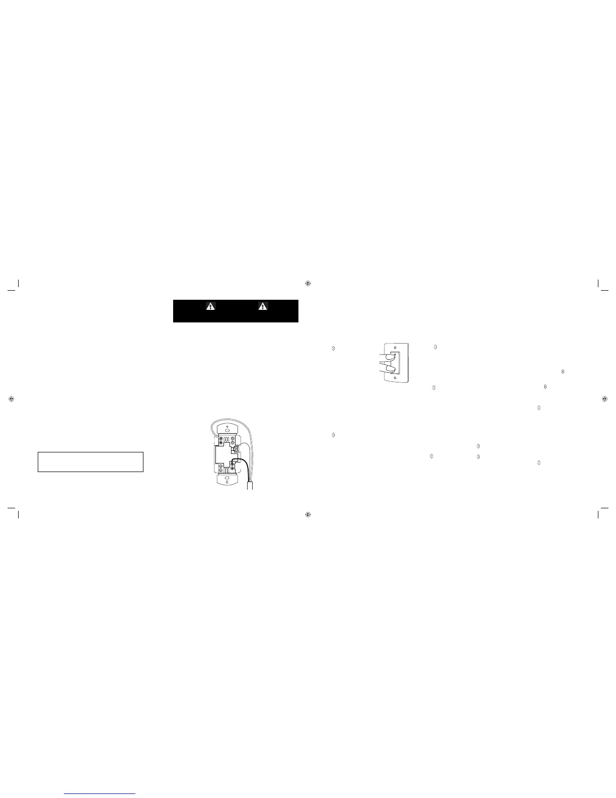
INSTALLATION
For ease of installation, manufacturer recommends use of a deep wall box. The
device is equipped with flying leads to simplify installation, however, if desired,
they may be removed by loosening the screw terminals.
1. Disconnect power to circuit by turning circuit breaker OFF before installation.
2. Remove existing wall plate and switch.
3. Strip existing wires 1/2”. If two wires will be connected to the same terminal
on a Miro device, both wires must be the same gauge (12AWG or 14AWG).
4. Wire the LINE (black), NEUTRAL (white) and GND (green or bare) supply wires
to the correspondingly marked terminals, according to the wiring diagram
below.
5. Attach the wall plate.
6. Switch the circuit breaker ON.
7. Make sure the LED on the DRD8 controller is lit. It should be yellow; if not, see
TROUBLESHOOTING.
ii_DRD8v2 07480r2.indd 5-8ii_DRD8v2 07480r2.indd 5-8 9/24/2007 4:08:58 PM9/24/2007 4:08:58 PM
 Loading...