Drawn by: CHANCE
Marketing:
Engineering:
Sheet: 1 of 2
the Watt Stopper Inc.
SANTA CLARA, CALIFORNIA
Title:
WI-200 Installation Instructions
Scale: Drawing # Original Drawing Date Rev #
1 : 1 86-0451 31May/95 1
All information in this drawing is the property of The Watt Stopper Inc. and cannot
be copied or used without the written approval of The Watt Stopper Inc.
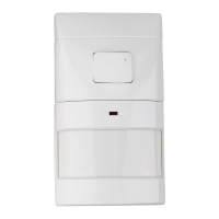
WI-200
120/277VAC
Universal PIR Wall Switch
Santa Clara, CA 95050
(800) 879-8585
SORDERING INFORMATIONSDIP SWITCH SETTINGS
SWARRANTY INFORMATION
The Watt Stopper
®
, Inc. warranties its products to be free of defects in materials
and workmanship for a period of five years. There are no obligations or liabilities
on the part of The Watt Stopper
®
, Inc. for consequential damages arising out of
or in connection with the use or performance of this product or other indirect
damages with respect to loss of property, revenue, or profit, or cost of removal,
installation or reinstallation.
Putting a Stop to Energy Waste
Santa Clara CA 95050 (800) 879-8585
86-0451
STROUBLESHOOTING
Lights will not turn on, LED does not flash:
1. Check the sensitivity settings. Make sure it is set to HIGH (DIP switch #8 ON).
2. Check all wire connections and verify the ground wire is tightly secured.
3. If lights still do not go on, call (800) 879-8585 for technical support.
Lights will not turn off:
1. If time delay is adjusted to maximum the lights will remain on for 30 minutes
after last motion is detected. Also, when the Manual On mode is being used,
the sensor acts as if it were in Automatic On mode for 30 seconds after the
lights turn off, and will turn the lights on when motion is detected without
having to push the AUTO/OFF switch.
2. To test if unit is operating properly, set time delay to minimum and move out
of the sensor’s view. Lights should turn off after 15 seconds.
3. If lights still do not go off, call (800) 879-8585 for technical support.
Sensing motion outside detection areas:
1. An opaque adhesive tape is included with the sensor and can be used to limit
the detection areas.
2. Adjust sensitivity to LOW (DIP switch #8 OFF) to reduce excessive sensitivity.
Sensor reset:
After checking a sensor for any possible malfunction it will be necessary to
reset the sensor. Turn the unit ON and warm it up. After 2 minutes, push the
AUTO/OFF switch 3 times and then check operation. This procedure will allow
the unit to reset properly.
Override function:
In the event of unit failure or if it is necessary to leave the lights on, set DIP
switch #1 to ON. This will turn the AUTO/OFF switch into a standard ON/OFF
toggle switch.
ASP-121
ASP-122
WI-200 Universal PIR Wall Switch; 120/277VAC, 60Hz
Blank plate for 2 gang box
2 gang box plate with switch option
Units and plates come in White (-W) and Ivory (-I).
Add color designator to catalog number when ordering.
WI-250 Universal PIR Wall Switch; 220-240VAC, 50Hz
WI-260 Universal PIR Wall Switch; 347VAC, 60Hz
Installation Instructions
DIP Switch #
15 seconds
4 minutes
6 minutes
8 minutes
10 minutes
12 minutes
14 minutes
16 minutes
18 minutes
20 minutes
22 minutes
24 minutes
26 minutes
28 minutes
30 minutes
2 minutes
Low (≈10FC)
Medium (≈50FC)
High (≈150FC)
Override
Manual On
Automatic On
Normal
Override
12345678910
X=On O=Off
X
X
X
X
XX
X
X
X
X
X
X
X
X
XX
X
X
X
X
X
X
X
X
X
X
X
X
X
X
X
X
X
X
X
X
X
X
XX
O
High
Low
X
O
O
O
OO
OOO
O
O
O
O
O
O
O
O
OO
O
O
O
O
OO
O
O
O
O
O
O
O
O
O
O
O
O
O
O
O
O
On Mode