Page 4
Sensor Valve Location
For the greatest effect, the valve should be located at a faucet with the greatest piping
distance from the hot water heater. If your home has a branched hot water line, more than
one Sensor Valve may be necessary. Additional Sensor Valve kits can be found at some
retail locations as well as Watts Premier website at www.wattspremier.com or by calling toll
free at (800) 752-5582.
NOTE: Do not use Teon tape or pipe dope on the Sensor Valve threads.
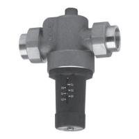
Sensor Valve Installation
3/8" Stop Valve Installation
1. Close both the hot and cold stop valves below the sink
(see Picture 3).
2. Place supplied rubber washers in female end of
adapters. Attach adapters to both “Cold Water Out” and
“Hot Water Out” ports of Sensor Valve. Finger tight plus
a quarter turn with wrench.
3. Disconnect existing supply line connection from both hot
and cold stop valves and then connect to adapter, attach
to Sensor Valve (see Picture 5).
4. Connect the new 1/2" x 3/8" ex hose to the hot water
stop valve (3/8" side) and the “Hot Water In” port (1/2"
side) of the Sensor Valve (see Picture 5). Connect the
remaining 1/2” x 3/8” ex hose to the cold water stop
valve.
5. Open both the hot water and cold water stop valves.
6. If desired, Sensor Valve can be mounted to the wall with
the mounting screws.
1/2" or Other Stop Valve Installation
1. Close both the hot and cold stop valves below the sink
(see Picture 3).
2. Place supplied rubber washers in female end of
adapters. Attach adapters to both “Cold Water
Out” and “Hot Water Out” ports of Sensor Valve.
Finger tight plus a quarter turn with wrench.
3. Disconnect existing supply line connection from
faucet connection leave stop valve connection
in place. Take disconected end and attach to
“Hot Water In” and “Cold Water In” connections
respectively
4. Connect the new 1/2" x 3/8" ex hose to the
already installed adapter (on Sensor Valve) (3/8"
side) and the faucet connection (1/2” side) for
both Hot Water and Cold Water respectively (see
Picture 5).
5. Open both the hot water and cold water stop
valves.
6. If desired, Sensor Valve can be mounted to the
wall with the mounting screws.
Picture 3
Picture 4
Picture 5
Hot Water
Out
Cold Water
Out
Cold Water
In
Hot Water
In

 Loading...