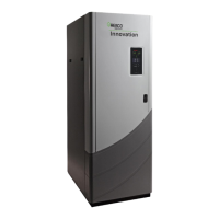
panels for maintenance. The disconnect switch should be mounted near the unit as illustrated in
Figure 1. Wiring conduit, EMT, or other wiring paths should not be secured to the unit, but supported
externally. Electricians should be instructed as to where the wiring conduit should be located, such as
away from the relief valve discharge, drains, etc. All electrical conduit and hardware should be
installed so that it does not interfere with the removal of any cover, inhibit service or maintenance, or
prevent access between the unit and walls or another unit.
4 Unit Wiring
A dedicated protected circuit should be provided from the power source to the unit. No other electrical
devices should be permanently wired on the same circuit. An emergency switch (electrical shutoff)
must be in series with the power to the unit. Refer to Figure 4 (120 VAC units) and Figure 5 (220 VAC
units) for the wiring connections to the terminal block contained in the unit’s Power Box.
Figure 4. 120 volt, Single Phase Wiring Schematic

 Loading...