2
Reduced Pressure Zone Backflow Preventers must be
inspected and tested periodically,
in accordance with local codes, to ensure proper operation of
check valves within the unit. A differential pressure gauge is
recommendedforTestNo.1ratherthanamanometerforthe
following reasons: It utilizes minimum time to perform the test.
It eliminates the necessity of closing the inlet ball valve which
could release pipe scale and foreign matter into the backflow
preventer. Only a slight amount of water is ‘spilled’ in test. A
mercury manometer could cause a pollution hazard.
Test Set Up
Reduced Pressure Zone Assembly
Close Valves A, B and C on Test Kit.
Connecthighsidehosetotestcock#2
Connectlowsidehosetotestcock#3.Closeshutoff#2.
Opentestcocks#2and#3.
Open vent valve C.
Open ‘high’ valve A and bleed to atmosphere until all the air
isexpelled.
Close valve A. Open ‘low’ valve B and bleed to atmosphere until
allairisexpelled.Close‘low’valveB.Close‘vent’valveC.
Connectventhosetotestcock#4.
Test Procedure
Reduced Pressure Zone Assembly
Field Test Equipment Required
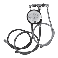
Reduced Pressure Zone Backflow Preventer Test Kit
Test No. 1
Purpose:TotestcheckvalveNo.2fortightnessagainstre-
verse flow.
Requirements: Valve must be tight against reverse flow under
all pressure differentials. Slowly open the high valve A and
the vent valve C, and keep the low valve B closed. Open test
cock#4.Indicatedpressuredifferentialwilldecreaseslightly.If
pressuredifferentialcontinuestodecrease(untiltheventopens)
checkvalve#2isreportedasleaking.
Test No. 2
Purpose:Totestshutoff#2fortightness.
Requirements:AfterpassingTestNo.1,continuetoTestNo.
2byclosingtestcock#2.Theindicatedpressuredifferentialwill
decrease slightly. If pressure differential continues to decrease
(approaching“zero”),shutoff#2isreportedtobe“leaking”.
Test No. 3
Purpose:TotestCheckValveNo.1fortightness.
Requirements: Valve must be tight against reverse flow under
all pressure differentials. Close high valve A and open test cock
#2.Closetestcock#4.Disconnectventhoseattestcock#4.
Open valves B and C, bleeding to atmosphere. Then closing
valve B restores the system to a normal static condition. Ob-
serve the pressure differential gauge. If there is a decrease in the
indicatedvalue,CheckValveNo.1isreportedas“leaking”.
Test No. 4
Purpose: To test operation of pressure differential relief valve.
Requirements: The pressure differential relief valve must
operate to maintain the “zone” between the two check valves
atleast2psilessthanthesupplypressure.Closevent valve
C. Open high valve A. Open the low valve B very slowly until
thedifferentialgaugeneedlestartstodrop.Holdthevalveat
this position and observe the gauge reading at the moment the
first discharge is noted from the relief valve. Record this as the
opening differential pressure of the relief valve.
NOTICE
It is important that the differential gauge needle drops slowly.
Closetestcocks#2and#3.Usevent hose to relieve pressure
from test kit by opening valves A, B and C. Remove all test
equipmentandopenshutoff#2.
Ball Type
Test Valves
(A)
(C)
(B)
Needle
Valve
Auxiliary
Test Cock
High Hose
(Color - Yellow)
Low Hose
(Color - White or Red)
Vent Hose
(Color - Blue)
Test Cock
No. 1
Test Cock
No. 2
Test Cock
No. 3
Test Cock
No. 4
Shutoff
No. 1
Check Valve
No. 2
Shutoff
No. 2
Check Valve
No. 1
909QT shown
CAUTION
!
To prevent freezing, hold Test Kit vertically to drain
differential gauge and hoses prior to placing in case.
No. TK-9 Model “A” Test Kit
 Loading...