EasyManua.ls Logo

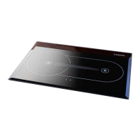
Webasto Diesel Cooker x100 User Manual

Webasto Diesel Cooker x100
38 pages
To Next Page IconTo Next Page
Page #1 background imageLoading...
Page #1 background image
Diesel Cooker x100
Service Manual
08-05-2008

Questions and Answers:

Webasto Diesel Cooker x100 Specifications

General IconGeneral
BrandWebasto
ModelDiesel Cooker x100
CategoryCookers
LanguageEnglish

Summary

General Information

Safety Notes and Legal Issues

General accident prevention regulations and current works safety instructions are applicable.

Use of the Cooker

The Webasto Diesel Cooker is designed for use in motorcaravans. It is not designed for use in boats.

Functions Description

System Description

Describes the safe diesel cooker with no open flame and how exhaust gases are handled.

Main Components - Operating Panel

Operating Panel Overview

Describes the function of the cooker's operating panel, including indicator lamps and switches.

Main Components - Fuel Pump, Glow Plug, Fans, Heat Exchanger

Fuel Pump

Explains the function of the fuel pump as a combined transport, metering, and shut-off system.

Glow Plug

Details the glow plug's role in ignition and its testing procedure.

Combustion Air Fan

Explains the voltage range and adjustment of the burning fan motor.

Heat Exchanger

Describes heat transfer from combustion to air via the heat exchanger and ceramic glass panel.

Main Components - Sensors and Control Unit

Temperature Sensors

Explains how T4 circuit measures heat sensor voltage and indicates overheating.

Control Unit

The central component for ensuring cooker function and monitoring operation.

Burner Assembly

Thermal Radiator

Details the thermal radiator and its installation/detachment procedures.

Operating Scheme

How the Device Works

Describes the device's operation through the control panel signal lights.

Technical Data

Electrical Components

Lists the voltage specifications for various electrical components of the cooker.

Fuel Specifications

Specifies the required diesel fuel quality and procedures for low-temperature fuel.

Technical Specifications Overview

Dimensions, Weight, and Performance

Details physical dimensions, weight, fuel consumption, and heating capacity.

Failure Detection Introduction

Fault Identification and Precautions

Introduces fault identification via LED codes and general troubleshooting precautions.

Troubleshooting Chart

Stove Not Responding Diagnosis

Flowchart for diagnosing and fixing issues when the stove does not respond.

Stove Not Starting Diagnosis

Flowchart for diagnosing and fixing issues when the stove fails to start.

General Failures

Cooker No Response Troubleshooting

Troubleshooting steps for when the cooker shows no response at all.

Cooker Start Failure Troubleshooting

Troubleshooting for the cooker failing to start, including pump and glow plug issues.

Specific Failure Symptoms

Combustion Air Blower Malfunction

Steps to diagnose and fix issues with the combustion air blower not functioning.

Smoking During Start-up Troubleshooting

Troubleshooting steps for when the cooker smokes during the start-up phase.

Additional Failure Scenarios

Cooker Turns Off Itself Troubleshooting

Troubleshooting steps for when the cooker switches off unexpectedly during operation.

Unstable Combustion/Smoking Troubleshooting

Diagnosing and resolving issues related to unstable combustion or smoking.

Failure Blink Codes

Glow Plug Malfunction Signal

Describes the yellow LED flashing pattern indicating a glow plug malfunction.

Air Fan Malfunction Signals

Describes LED flashing patterns for combustion and cooling air fan malfunctions.

Under-Voltage Signal

Explains the yellow LED flashing pattern indicating low operating voltage.

LED Status Indicators

Yellow LED Error Signals

Details various yellow LED signals for malfunctions, voltage, and test phases.

Red LED Error Signals

Explains red LED signals for burning indicator, overheating, and lock-up conditions.

Updating and Repair Overview

Control Unit Software Update

Instructions for updating the control unit software using XPS software.

Software Update Procedure Steps

File Transfer and Connection

Steps for copying program files and connecting the PC to the control unit.

Parameter Update Methods

Describes two methods for updating parameters on a single device or all devices.

Test Program Usage

Test Device Functionality

Explanation of the 'Test' device for investigating control unit condition.

Maintenance Coupler Measurements

Details measurements to be taken from the J6 connector during unit operation.

Burner Maintenance Procedures

Thermal Radiator Removal and Installation

Instructions for removing and fitting the thermal radiator from/to the burner cylinder.

Fuel Needle Installation

Fuel Needle Orientation Guide

Guidance on the correct orientation of the fuel needle during installation.

Glow Plug Servicing Guide

Glow Plug Malfunction and Testing

Describes malfunctions resulting from thermal overload and testing procedures.

Glow Plug Installation Instructions

Instructions for safely changing the glow plug, including torque specifications.

Heat Exchanger and Glass Panel Service

Glass Panel Replacement and Gluing

Steps for changing a broken glass panel and applying adhesive for proper seating.

Pump Boost Functionality

Pump Boost Operation Details

Details the function of the Pump Boost for filling fuel hoses during installation and maintenance.

Electrical Connections Overview

Control Unit Outer Connections

Diagrams and pin assignments for outer connections of the control unit.

Control Unit Wiring Diagram

Electrical Connections Schematic

Schematic showing electrical connections for the control unit, panel, and thermo element.

Maintenance and Service Procedures

Basic Maintenance Steps

Outlines basic maintenance steps like cleaning the burner and checking the glow plug.

Fuel Input Measurement and Adjustment

Procedure for measuring fuel consumption and adjusting input for optimal performance.

Combustion Analysis and Adjustment

O₂ and CO₂ Analysis

Methods for analyzing combustion gases and interpreting results for adjustments.

Combustion Air Speed Adjustment

Steps for adjusting the burning fan speed for minimum and maximum settings.

Control Unit Configuration

Parameter Settings and Jumper Configuration

Instructions for selecting and configuring device parameters using jumpers and software.