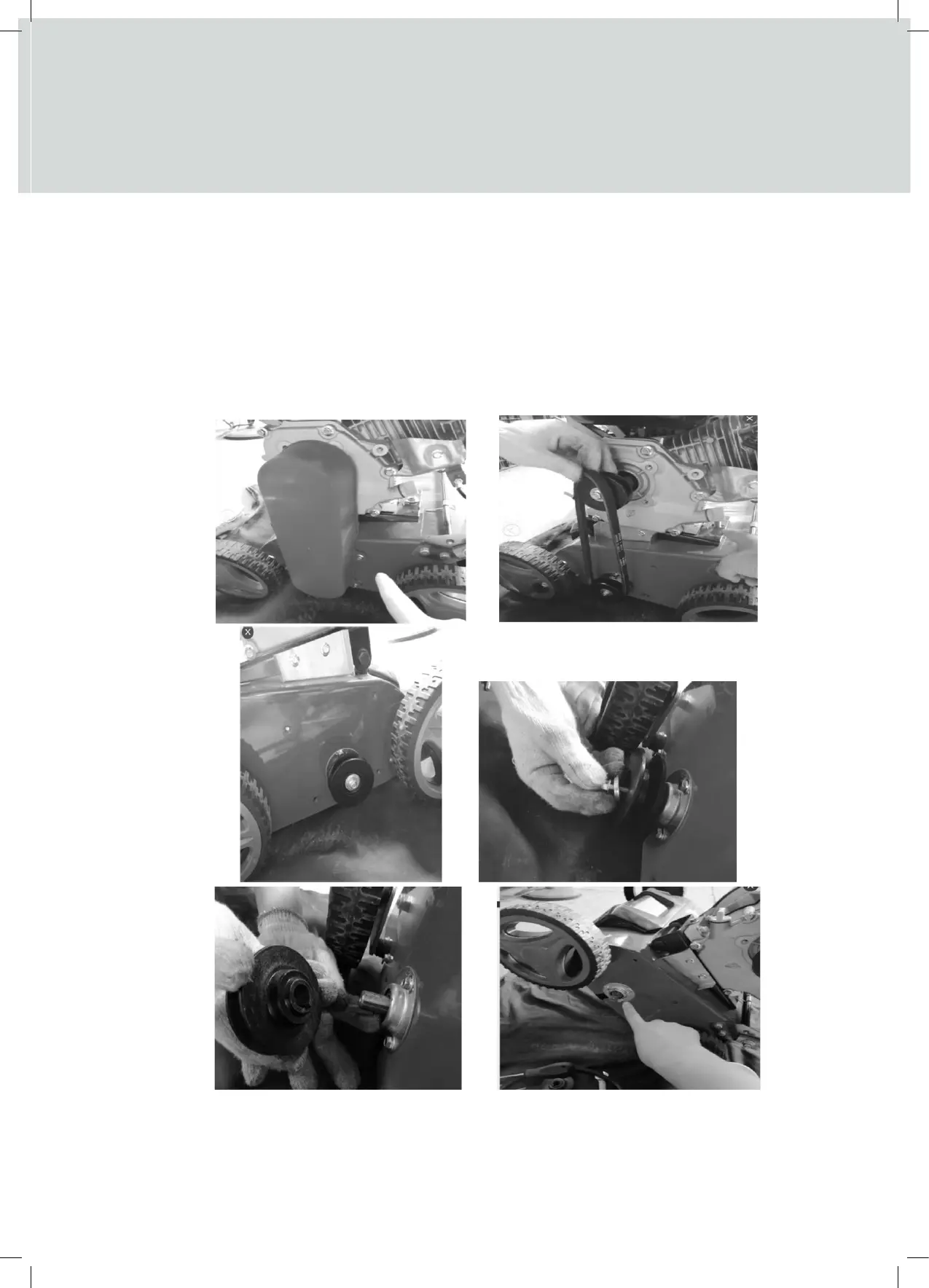
9. Ensure the fixing holes of the mounting cover and bearing cover on the right side of the machine are
10. Repeat step 10 with the mounting block and cover on the left side of the machine and assemble with
11. Place the blade belt over the bottom & top pulley (Fig. 2)
12. Refit the bottom belt pulley to the left side of the machine deck (Fig. 5, 4 & 3). Ensure the pulley
13. Adjust bolt in Fig. 10, located under engine mounting plate to match image.
14. Refit belt cover (Fig. 1).
Fig. 3 Fig. 4
Fig. 5 Fig.6
CHANGING THE WORKING DEPTH
IMPORTANT:
Turn the engine off, prior to making any height adjustment.
To set the working depth, push the height adjuster lever (4) gently away from the deck and move up or
down the height gauge, set to the required depth and then lock the lever back into position.
Moving the lever to the right raises the blade and to the left lowers the blade from 5 to ‐15mm.
TRANSPORT
When moving the machine to and from the work area, always ensure the height adjustment lever is placed
in the highest cutting height to ensure the blades/tines are not in contact with the ground.
CHANGING THE CYLINDER - MINIMUM TWO ADULT ACTION
WARNING
When changing the cylinder, ensure suitable hard-wearing gloves are worn at all times.
CAUTION
Only use genuine blade/tine cylinders with this machine.
The equipment can be assembled with the Dethatching (blades) or Scarifying (Spring Tines) cylinders. Only
replace the cylinder with an original Webb product, to ensure top performance & safety. To change the
cylinder, proceed as follows. We recommend this is undertaken by a minimum of two adults and that
suitable hard‐wearing gloves are worn at all times.
1. Remove the belt cover from the machine. (Fig. 1)
2. Remove the bottom pulley & blade belt (Fig. 3, 4 & 5)
3. Loosen the bearing mounting block away from the left side of the machine deck, which was positioned
underneath the bottom pulley, by removing the three fixing screws. (Fig. 6).
4. Loosen the bearing cover away from the height adjuster lever side of the machine (right), by removing
the three fixing screws (Fig. 7).
5. With the machine tipped backwards and held by a second person, slide the cylinder from the machine.
6. Remove the bearing cover, mounting block and mounting cover from the ends of the removed cylinder
(Fig. 9)
7. Slide the mounting covers onto each side of the cylinder to be fitted. Now fit the bearing cover and
mounting block to either end of the cylinder. (Fig. 8)
8. With the machine tipped backwards and held by a second person, slide the cylinder on to the machine
 Loading...