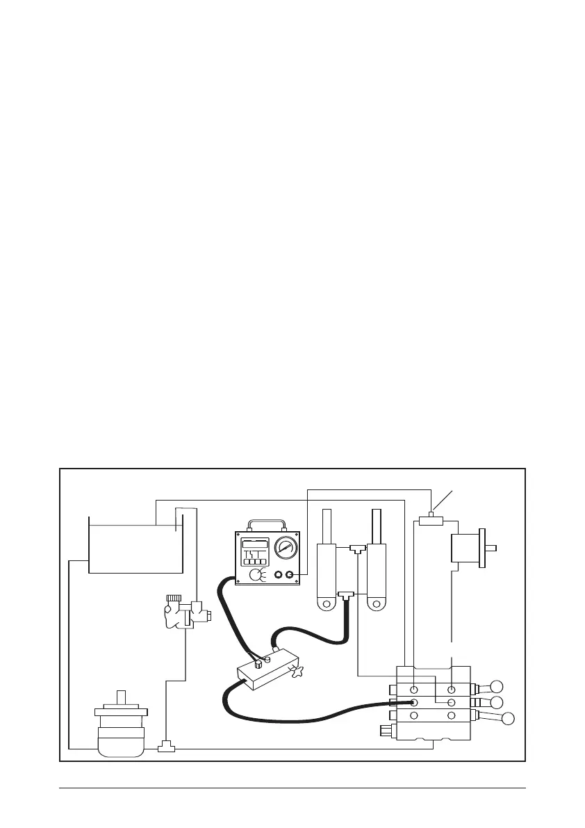
Pump
Relief
Valve
Flow Block
& Load Valve
Test Hose
Relief
Valve
Directional Valve
Motor
Remote
Flow
Block
DHCR
Readout
It is not unusual for a relief valve to start cracking open below the maximum
pressure setting causing considerable leakage and loss of machine
performance. The cracking pressure can be checked by increasing the
pressure slowly and noting the pressure at which the flow starts falling rapidly
to zero. The maximum relief valve setting is when the flow is at zero.
4.3 Control Valve. Cylinder ‘TEE’ Test
4.31 Put control valve in power position. (On multiple spool valves, only one spool
should be in a power position at any one time). The cylinder should be
extended to the end of the stroke.
4.32 Close tester loading valve slowly while recording pressures and flow rate.
4.33 Repeat 4.32 for power position, for all spools of all control valves.
4.331 If all components are in good operating condition, pressure and flow
measurements should be the same as in the pump test paragraph 3.0.
4.332 If the decrease in the flow of any control valve position is noted, leakage is
indicated in this control valve or cylinder. See paragraph 4.4 for test routine
to determine which is at fault.
4.333 If the decrease in flow is the same for the control valve(s) in all positions,
it indicates the relief valve is at fault. (Note: This can also indicate some
other leak is present in the control valve such as defective casting - but
always check the relief valve FIRST)
4.4 Additional test to locate fault in control valve or cylinder (see paragraph 4.332).
Disconnect line to cylinder and plug valve port.
4.41 Place control valve handle in position where greatest decrease of flow was
noted.
4.42 Close tester loading valve and record both pressure and flow.
4.43 If the SAME decrease in flow is noted as in test per paragraph 4.332 then the
control valve is at fault. HOWEVER, if the flow readings are now higher and
comparable to the other control valves, then a faulty cylinder is indicated.
9
Drawing B1
 Loading...