`çãéäÉíÉ=háí==j^k=
`çãéäÉíáçå=çÑ=~ëëÉãÄäó=Öêçìéë
707
13
26
19
706
15
15
707
13
26
568
655
19
19
713
1256
713
289
706
4
4
483
1257
26
16
13
26
16
13
12
96
383
93
372
383
96
12
95
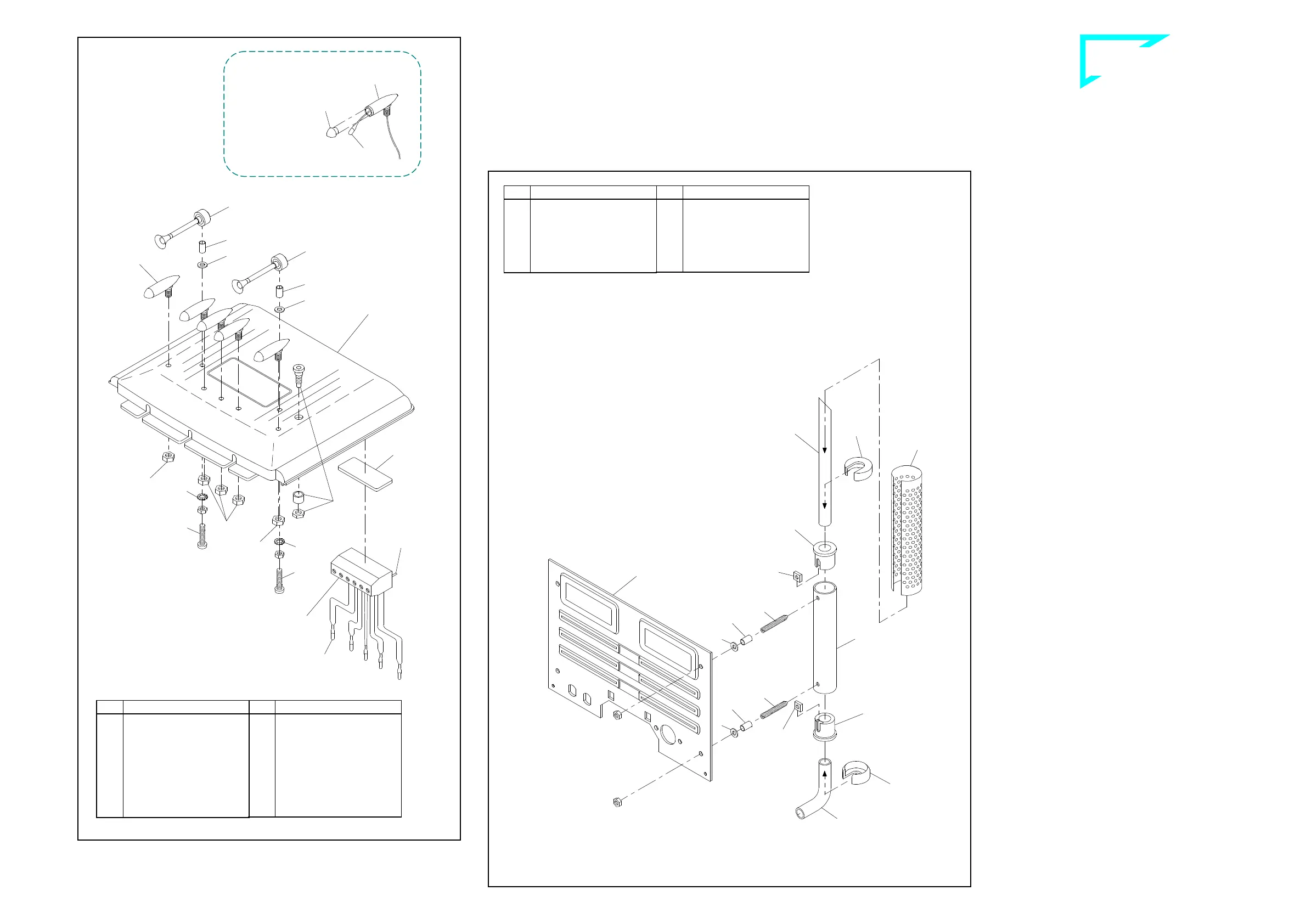
P ^ëëÉãÄäáåÖ=íÜÉ=êççÑ=ëÉÅíáçå=
3.1 Antenna socket and horns
Affix the components for the antenna socket 568 as shown in the il-
lustration. Please note that the antenna cable from the remote con-
trol receiver will have to be soldered to the antenna socket.
The horns 707 are fitted with bushings 26 and washers 13 and then
affixed, through the holes provided in the roof 1263, using screws 4,
nuts M3 and serrated washers 15.
3.2 Roof lamps
Install a bulb 713 in each of the roof lamps 706, threading the leads
through the lamp housings first. The cables are easier to thread if
you twist the two conductors together and bend the ends slightly.
Pointed tweezers can help in pulling the cable through. Do not pull
the bulbs too far into the lamp housings; the bulbs should protrude by
2 to 3 mm. After the roof lamp lenses 289 have been pressed onto
the lamp housings, the housings are inserted in the holes in the roof
and secured with nuts 19.
The bulb leads and the red/black cable from the switch panel are at-
tached to the terminal strip - see Section 23.3 and ill. 23. Use adhe-
sive pads 655 to affix the terminal strip under the roof so that the ca-
bles are not visible inside the cab.
Q oÉ~ê=é~åÉä=ëÉÅíáçå=
4.1 Assembling the exhaust system
The illustration is showing the assembly of the left side only. Please
mount the right side in the same sense.
Slide one square nut 12 each into the depressions at the exhaust
caps 96. Now slide these caps into the muffler 93 so that the nut is
located behind the hole. Slide the exhaust tail pipe 95 from above
into the muffler cap until catching; clamp it in place with a stud 16.
Ensure that the tip of the exhaust pipe points is aligned with the nut.
Follow the same procedure for the exhaust manifold 483. Its lower
opening must also be aligned with the nut. Then a bushing 26 and
washer 13 are slid onto the two studs.
Now use the stud bolts to insert the exhaust system through the mat-
ing holes at the rear panel 1257, and afterwards secure it with the
M3 nuts. Press the fixing caps 383 from above and below onto the
muffler and slide the exhaust shield 372 over them.
57-e.DOC / K-MAN Page 3
Assembling the roof section ill. 3
Rear panel section ill. 4
B-57-2
For threading the bulb leads
see proper text
Please clip
off the
solder pins
for roof lamps
Qty.
No. Assembly part
4
96
Exhaust cap
2
372
Exhaust shield, chromed
4
383
Fixing cap
2
483
Exhaust manifold
1
1257
Rear panel, Complete
Kit MAN “C”
Qty.
No. Assembly part
4
---
Nut M3
4
12
Square nut M3
4
13
Washer 3.2
4
16
Stud bolt M3 x 18
4
26
Bushing 4 x 0.5 x 7
2
93
Muffler 80mm
2
95
Exhaust tail pipe
Qty.
No. Assembly part
1
655
Adhesive pad,
double-sided
5
706
Roof lamp, chromed
2
707
Horn
5
713
Bulb 3V
1
1256
Roof, Complete Kit
MAN “C”
1
---
Terminal strip for roof
lamps, 6-pole
Qty.
No. Assembly part
2
---
Nut M3
2
4
Screw M3 x 16
2
13
Washer 3.2
2
15
Serrated washer 3.2
5
19
Nut M4
2
26
Bushing 4 x 0.5 x 7
5
289
Lens for roof lamp,
orange
1
568
Antenna socket,
complete
 Loading...