TECHNICIANS' manual 77 of 100
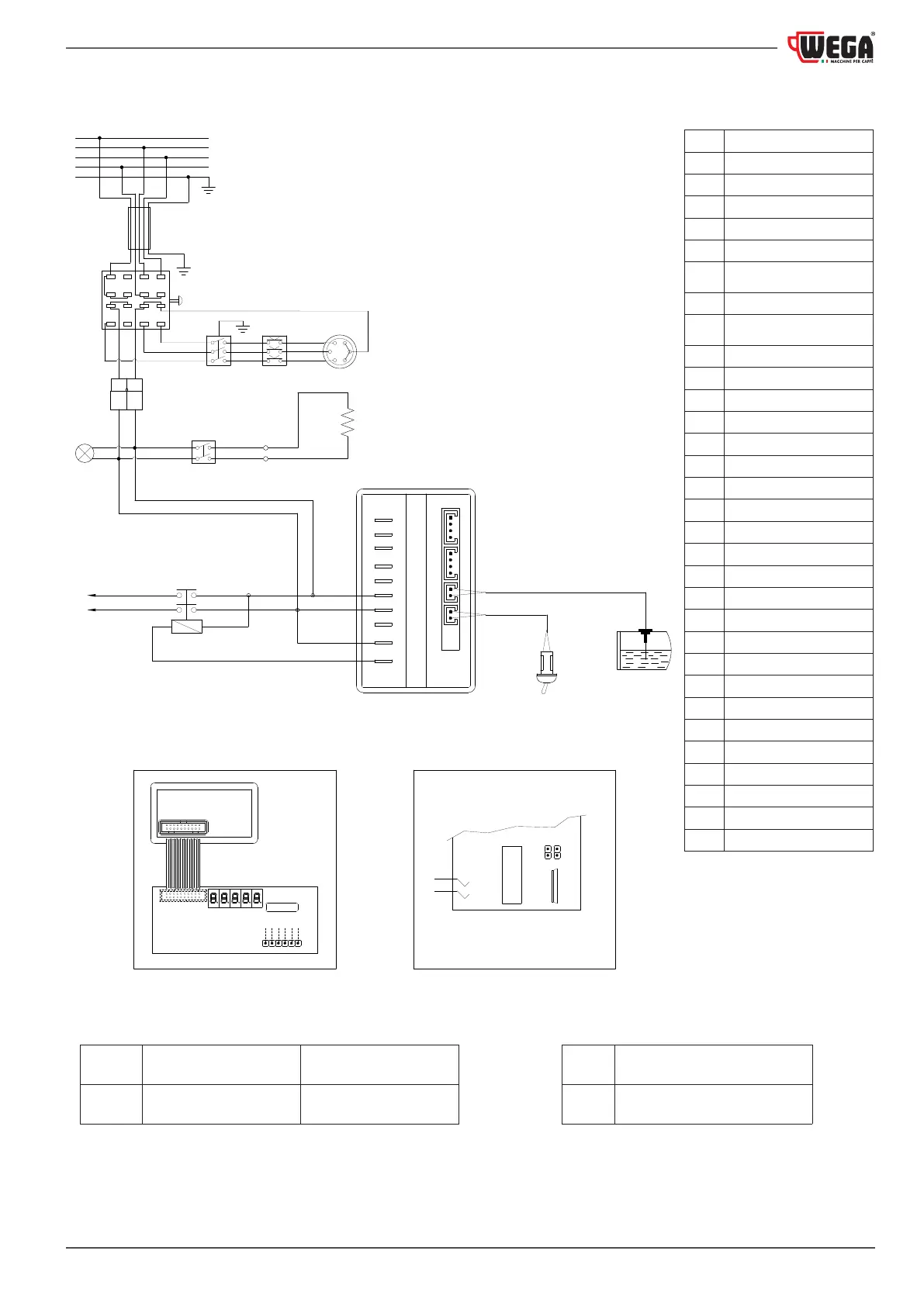
12.7.15 Wiring diagram code WY18090018 - WY18090019
FIG. A
Base card - display card connection
detail
FIG. B Jumpers inside view
(
*
) Fuses for UL versions where
a plug with a capacity greater
than 30 A is installed
CT
SCT
LA
PR
SA
CO
RE
400V
IST
R
S
T
N
MA
BL NE GR GV
CAB
MA
BL
FA5
FA4
FA2
FA1
CN1CN2CN3
CN4
IP
TG
SCB
CM
SCD
P2
P1
FA2
FA1
RL
BA
FIG. A FIG. B
MC
SL
CAL
13 9 5
1
3
71115
16 12 8
4
2
610
14
BI White
BL Blue
BA Battery
CAB Power cable
CAL Heating unit
CM Membrane connection
CN1
Power supply and services
outputs
CN2 Not managed
CN3
Heating unit level probe
connect.
CN4 Programm. inter. connect.
CN5 Connect. with display card
CO Power switch
CT Power supply connector
CV1 Volumetric counter
GV Yellow-green
IP Programming switch
IST Cup warmer switch
LA Indicator light
MA Brown
MC To the machine
NE Black
PLT Tea button
PR Pressure switch
RE Heating element
RO Red
RL Relay
SA Safety heating element
SCB Base card
SCD Display card
SL Heating unit level probe
TG Main remote switch
VE Green
MOVABLE
JUMPER
INSERTED NOT INSERTED
JP1 Flow meter hardware
Pre-set dispensing volume
software
 Loading...