5
2.3.2 Connection to a Personal Computer
The 9 Pin, Female, SUB-D, PC [RS-232] & PLC [RS-485] Port on the back of the unit is the
programming port (PC Connector) and RS485/422 communications port for connecting to a controller.
Connection
This port can be attached to a Computer via a special DB9 Female to
DB9 Female cable provided with the unit. (P/N: MT5_PC)
Port Activation This port is activated automatically by the PC during on line simulation,
download and upload activities.
The Programmer Port cannot simulate, download or upload to the
MT-500 while it is on line with the controller at the same time. The
MT-500 must be put into “RDS” mode with the EasyManager applet
first.
Pin Designations
PC [RS-232] &
PLC [RS-485]
Pin assignment of the 9 Pin, Male, SUB-D PC [RS-232] &PLC
[RS-485] Port. (Only MT5XXXE4 has AUX RS485)
Pin# Symbol PLC[RS485]
4 wire
PLC[RS485]
2 wire
Aux[RS485]
(only E4 series)
PC[RS232]
1 Rx- Rx- Data-
2 Rx+ Rx+ Data+
3 Tx- Tx-
4 Tx+ Tx+
5 GND Signal Ground
6 Data- Data-
7 TxD Transmit
8 RxD Receive
9
Data+ Data+
MT-500 to PC
MT5_PC Cable
Configuration
MT-500
RS232/485
PLC
RS485
PC
RS232
Rx- 1 1 1
Rx+
2 2
2
Tx- 3 3 3
Tx+ 4 4 4
GND 5 5 5
Data- 6
6 6
TxD 7 7 7
RxD 8 8 8
Data+ 9
9 9
2.3.3 Connection to a Printer
The printer port on the back of the unit is a Parallel printer port and is compatible with most printers that
accept parallel connectors.
Print Out
The MT-506TE4 and MT-506SE4 models have print out capabilities.
The printer port transmits data when a printable object is activated.
MT-500 support compatible with EPSON ESC/P2 printer. For details,
contact your local distributor.
6
Note: Connect printer the distance can’t longer than 5m.
Pin Designations
PRINTER
The printer port need an option 15 Pin D-SUB to 25 Pin D-SUB
cable(P/N: MT5_PRN).
2.3.3 Dip Switch
Touch Screen Test mode: In this mode when you touch the screen, the screen will display a “+” sign.
So you can test the touch screen was accurate.
RDS (Remote Debug & Simulation) mode: Used for simulation and download/upload.
When E4 series insert a CF card will appear a green button on screen right and bottom side.
Press this button to startup the project download procedure.
Touch Adjust (Touch screen calibration) mode: Used to calibrate the touch screen.
Application (On line operation) mode: This is the normal operating mode of the EasyView; the
EasyView will start from the startup window of the project download.
2.4 CE Requirements
EU directives that apply to the MT-500 Series:
EMC Directive (89/336/EEC, 92/31/EEC, 93/68/EEC) electromagnetic emissions and immunity
Machinery Directive (89/392/EEC, 91/368/EEC, 93/44/EEC, 93/ 68/EEC) machine safety
MT500 products will be CE-marked to indicate compliance with the EMC Directive.
The MT-500 Series has been designed to operate satisfactorily in electromagnetic noise (immunity) and
without emitting high levels of electrical noise into the environment (emission). The units are designed to
meet European Community standards when installed per the wiring instructions in this manual.
Compatibility
Standards
The MT-500 has been designed to meet electromagnetic compatibility for industrial
environments.
• CISPR (EN 55011) Group 1, Class A Radiated Emissions levels
• EN50081-2 Generic emission standard, industrial environment (Also US FCC
Class A)
• EN50082-2 Generic immunity standard, industrial environment
SW1 SW2 Mode
ON ON Touch Screen Test mode
OFF ON RDS (Remote Debug & Simulation) mode
ON OFF Touch Adjust (Touch screen calibration)
mode
OFF OFF Application (On line operation) mode
MT5_PRN
Printer Cable
7
3.0 Specifications
MT506TE4 MT506SE4 MT506TV4 MT506SV4 MT506LV4
Hardware Specification
Display 5.7" TFT 5.7" STN 5.7" TFT 5.7" STN 5.7" Blue
Brightness 300 cd/m2 150 cd/m2 300 cd/m2 150 cd/m2 60 cd/m2
Color 256 color 256 color 256 color 256 color 4 gray scale
Contrast Ratio 60:1 30:1 60:1 30:1 15:1
Resolution (WxH dots) 320 x 240 320 x 240 320 x 240 320 x 240 320 x 240
Back light CCFLx1 CCFLx1 CCFLx1 CCFLx1 CCFLx1
CCFL life time 40,000 hr. min. 25,000 hr. min. 40,000 hr. min. 25,000 hr. min. 15,000 hr. min.
Touch panel 4 wires resistive type
Touch Accuracy 1.5mm
Surface Hardness
4H
Serial Interface HMI-PC (RS-232)
HMI-PLC (RS-232/485)
AUX port HMI-AUX(RS-232/RS-485 2w) N/A
Ethernet port 10Mbps N/A
Processor 32bit RISC CPU 200MHz
Flash Memory
2MB 1MB
Recipe memory 128KB
Compact Flash card slot Ye s N/A
RTC Ye s
Parallel printer port
Ye s N/A
System Diagnostic
Power failure detection
General Specification
Input Power 21-25 VDC
Power Consumption 370 mA@24VDC 220 mA@24VDC 370 mA@24VDC 220 mA@24VDC 200 mA @24VDC
CE Complies with EN50081-2 and EN50082-2 standards
FCC Complies with FCC Class A
Voltage resistance 500VAC (1 min.)
Isolation resistance Exceed 50MΩ at 500VDC
Vibration endurance 10 to 25 Hz (X,Y,Z direction 2G 30minutes)
Protection structure IP65 front panel (O ring seal)
Operating Temperature 0~45°C
Operation humidity 10-90% RH (non –condense)
Enclosure Plastic PBT + PC
Dimensions WxHxD 204x150x48mm
Panel cutout dimension 192 x 138 mm
Wei gh t Approx. 0.8 kg
Software
Screen Editor Software EasyBuilder 500 V2.5.0 or later
8
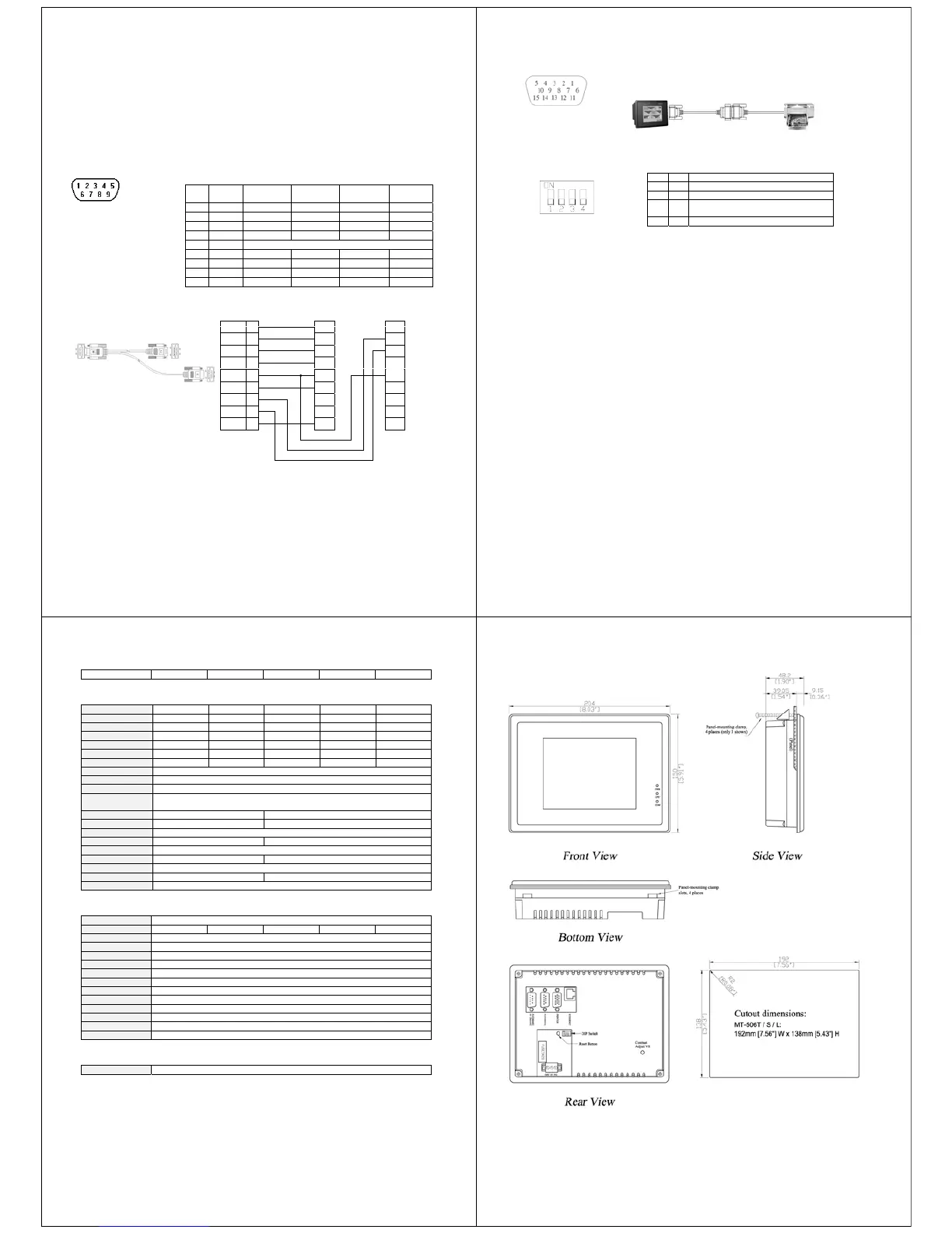
4.0 Dimensions of MT-506
a. PLC[RS485]/PC[RS232]
b. PLC[RS232]
c. PRINTER port (only E4 series)
d. Ethernet port (RJ-45) (only E4 series)
a

 Loading...