User Manual Specifications 67
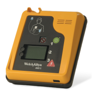
Defibrillator
Output MRL Orbital™ Biphasic Truncated exponential
Energy Sequence (user configurable) Shock 1: 150 J, 200 J
Shock 2: 150 J, 200 J, 300 J
Shock 3: 150 J, 200 J, 300 J, 360 J
Charge Time from “Shock Advised” 4 sec. to 150 J
8 sec. to 200 J
15 sec. to 360 J
Analysis Time 4-16 sec.
Combined Analysis and Charge Time From start of analysis to shock ready:
from power up
after 6 shocks
Less than 20 seconds to 200 J
Less than 30 seconds to 360 J
Audible Prompts 18 audible prompts
Visual Prompts 20 text screen prompts
Controls Four buttons - On/Off, Shock, and 2 software-configurable buttons
Waveform Details The table below provides details of the biphasic truncated exponential waveform
delivered by the AED 10 (set to Emax) when connected to resistive loads of 25
through 175 Ω. The waveforms are characterized by typical values for peak
current (I
p
), duration of the first output phase, and duration of the second output
phase. Values are within 10%.
Patient
Impedance (Ω)
I
p1
(Amps)
I
p2
(Amps)
t
phase1
(ms)
t
phase2
(ms)
25 52.2 35.7 5.6 3.8
50 26.5 16.9 11.6 7.7
75 17.5 11.8 16.6 9.9
100 13.3 9.3 18.8 9.9
125 10.5 7.7 19.9 10.3
150 8.9 6.8 20.2 10.3
175 7.5 6.0 20.4 10.3
Output Energy Accuracy ±10% or 1 J (whichever is greater) into 50 Ω impedance
±15% or 1 J (whichever is greater) into any impedance from 25 Ω to 125 Ω
Typical transthoracic impedance with properly applied Welch Allyn defibrillation
pads is under 125 Ω.
p1
phase 1
phase 2
I
p2
 Loading...