12
12-16-08
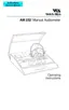
Rear panel connectors and indicators (see Figure 2)
Figure 2: Rear panel.
R1 - Power input jack (5-pin DIN Connector) with front panel illustration showing its
location and a rear panel label giving the input power specifications.
R2 -
!
Attention, consult accompanying document for instructions or warnings
pertaining to these parts.
R3 - Earphone output jacks (standard phone jacks). Front panel illustration shows
left and right phone.
R4 - Response handswitch input jack (standard phone jack) with front panel illustra-
tion showing location.
R5 - Entry by qualified service personnel only.
Note: The above symbol is located inside the storage compartment. It denotes a
Type B, Class II product per IEC 878 as referenced in IEC 60601-1.
 Loading...