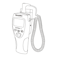
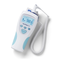
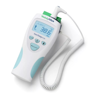
Technical Manual
SureTemp
®
Model 670/SureTemp 4
®
Model 675 13
THEORY OF OPERATION
Technical Overview
The heart of the Model 670 and Model 675 is comprised of three custom integrated circuits which provide
most of the microcontroller and analog circuit functions. All control and display functions are governed by
the microcontroller (U2), all analog interfacing to the microcontroller, probe, horn and backlight is provided
by U1, and operating parameter data is handled by the EEPROM U3.
Probe resistance measurements are made by ratioing pulse widths which are generated by sequentially
switching in two calibration resistors and the probe thermistor. These pulse widths are measured by the
microprocessor which calculates the probe resistance. The actual probe temperature is then calculated from
the probe resistance.
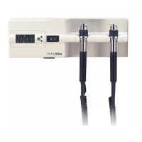
FACTORY
CALIBRATION
SYSTEM
CONNECTOR
M38203
MICROCONTROLLER
PULSE TIMER KEY
BACKLIGHT/RECALL KEY
MONITOR/NORMAL SW
EEPROM
F/C SWITCH
PROBE SWITCH
HORN
PROBE
HEATER
BACKLIGHT
PULSE WIDTH
A/D
CONVERTOR
LCD REFERENCE
PROBE
4 MHZ CRYSTAL
_
factory_cal_sw pulse_timer
clear_to_send
RXD _blight_recall
TXD
request_to_send _monitor_mode
eeprom_ser_out _celsius_mode
eeprom_clock
eeprom_select _probe_out
eeprom_ser_in
_eeprom_pwr
_horn_on
_heater_Q
_heater_C
_heater_tst
LCD
_heater_pwr
DISPLAY
backlight_pwr
ad_power
_ad_trigger
probe_ad_select
ptb_ad_select
hical_ad_select
lowcal_ad_select
batt_ad_select
_counter_gate
rectal_probe
axillary_probe
rs232_pwr
FIGURE 3 - SYSTEM BLOCK DIAGRAM
 Loading...