Technical Manual
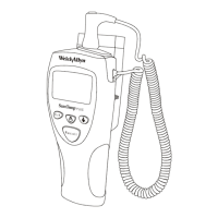
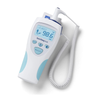
SureTemp
®
Model 670/SureTemp 4
®
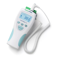
Model 675 15
Normal Mode, Model 675
The Oral probe is pre-warmed using a pulse width modulation (PWM) controller to 33.9
°
C (93
°
F) upon
extraction from the storage channel. When the probe is first extracted and colder than 33.9
°
C, the pulse
widths are at a maximum percentage ON vs. OFF to warm the probe quickly. When the probe reaches
33.9
°
C, the pulse widths narrow to a duty cycle just enough to maintain temperature. When the probe is
placed in the mouth, the heat supplied by the mouth makes the pulse widths reduce to zero. This reduction
to zero (and the probe being at least up to 33.1
°
C) triggers the start of the prediction algorithm.
The shape of the rising temperature curve is monitored and the best fit to a curve is found. When the curve
fit is stable, the final predicted temperature is displayed.
If the prediction criteria explained above are not met within 15 seconds of starting the prediction process, it
will automatically switch to Monitor mode.
If the ambient temperature is above 33.9
°
C (93.0
°
F) the unit will automatically switch to Monitor mode.
Rectal probes are not prewarmed and the operation is similar to that in the Model 670.
Power Supply
Power is drawn from the three “AA” alkaline cells directly to the circuit electronics. The voltage from the
batteries is unregulated but filtered for noise by capacitor C9. The power supply voltage will range from
about 4.8 volts with new batteries to 3.2 volts at shut down. The thermometer has two low battery voltage
indicators. The first is a warning that batteries are getting low and is indicated by the battery icon flashing in
the display. This begins when the batteries fall to about 3.4 volts. Accuracy is not effected during low
battery warning indication. When the batteries fall to approximately 3.2 volts, the low battery error condition
is defined to exist. Operation is halted and the E3.0 error message is displayed.
At this point, the batteries must be replaced and the thermometer electronics reset. See the Reset
Self/Tests section on page 16 and in the Operational Characteristics section on page 2.
Microprocessor Usage
Inputs
to the microprocessor include LCD voltage regulator lines (pins 6,7 and 8), user switch lines (pins 10,
11, 23, 39 and 40), A/D done output signal (pin 13), low battery signal (not used by software)(pin 14), probe
warmer self check lines (pins 15 and 16), probe type identification lines (pins 17 and 18), serial port lines
(pins 19 and 22), EEPROM U3 data line (pin 25), factory calibration mode select line (pin 26), reset line (pin
27), slow clock (not used) (pin 28), and the 4MHz microprocessor clock (pin 30).
Outputs
from the microprocessor include LCD driver lines (pins 1 through 5, 57 through 72, and 74 through
80), horn control line (pin 12), serial port lines (pins 21, 24 and 53), slow clock (not used) (pin 29), the 4MHz
microprocessor clock (pin 31), battery voltage measure line (pin 41), A/D control lines (pins 42 through 45, 51
and 56), EEPROM control lines (pins 46, 47,48 and 50), LCD voltage regulator control line (pin 49), backlight
control line (pin 52), probe warmer control lines (pins 54 and 55).
Reset/Self Tests
Upon battery installation, (assuming that the electronics has been discharged sufficiently by pressing a user
button with batteries removed) the microprocessor receives a power up reset signal from the components
associated with the reset line U2-27. During short duration power dropout capacitor C1 is discharged quickly
through D6. When power is applied continuously, C1 is charged slowly through R7 providing an active low
reset to the microprocessor.
 Loading...