Welch Allyn, Inc.
38 SureTemp
®
Model 670/SureTemp 4
®
Model 675
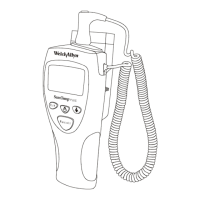
THERMOMETER REASSEMBLY
Note:
Most of the screws in the unit are plastic thread rolling screws and do not require excessive tightening
which will strip out the case plastic threads.
1. If the electronics assembly has been removed from the mid-frame, solder the battery wires and the horn
wires to the main PCA, then slide the main PCA into the two retaining tabs near the center of the mid
frame and insert the top of the main PCA under the two plastic tabs towards the top of the mid-fame.
2. Lay the front case face-down on a flat surface.
3. Ensure that the display window has been cleaned and installed in the front case, with its slightly rough,
scratch resistant surface facing outward.
4. Carefully slide the display board assembly under the retaining tabs at the top of the front case.
5. Gently press the bottom of the display board until it contacts the screw wells in the front case and install
the two shortest display board retaining screws.
6. Install 3 “AA” batteries according to the battery polarities marked inside the battery compartment. Verify
that the thermometer completes self-test, and the display goes blank.
CAUTION: Incorrect battery polarity may result in damage to the thermometer.
7. Install the back case.
8. Install the battery door.
9. Insert all four screws into the back case, but leave loose. Note that there are two shorter screws for the
display area, and one machine screw for the Battery Door.
10. Insert one of the neck strap pins into its receptacle and tighten the screw adjacent to the receptacle.
11. Insert the other neck strap pin into its receptacle and tighten the screw adjacent to it.
12. Tighten the two remaining screws.
13. Install the
°
F
-
°
C
/
NORMAL
-
MONITOR
label (at the top of the thermometer).
14. Plug the probe into the thermometer.
15. Insert the probe into the probe storage channel. Verify that the thermometer displays “OrL” (briefly for
Model 670 and for several seconds for Model 675) then goes blank.
 Loading...