The Company, L.L.C. Oklahoma City, Oklahoma Tel: (405) 672-6660 Fax: (405) 672-6661
wellmarkco.com
© The WellMark Company • Litho USA • All registered trademarks are the property of their respective owners. • IOM-6900 090923
Specifications
Connections
Output
General
Process 2” MNPT Std.
3”, 4”, 5”, 6” Flanges, Yale and Hammer Union
Configurations also available
Pilot 1/4” FNPT
Throttle (Proportional) 3-15 psig
Snap-Acting 0 to Full Supply (Pilot rated to psi)
Maximum Working Pressure (CWP) 1500 psi
Pilot Operating Pressure Normal: 20 -30 psi
Overpressure Protection: Gauges are the limiting factor.
75
psi minimum Max.
Temp. Limits -40°F to + 00°F
(Higher temperatures available - Consult factory)
Displacer PVC (165°F max.)
Delrin (200°F max.)
Phenolic Screw-on (275°F max.)
Phenolic Slip-on (400°F max.)
Sight Glass Polycarbonate
Seals Buna-N standard (others available)
2
(Pyrex® available)
Materials
Over-pressure of this control or installation of the
control in applications which may see pressure
levels beyond those for which the control is
designed may result in leakage and/or catastrophic
failure. This failure could result in leaking gas, or
produced liquid, damage to surrounding equipment
and/or environment, personal injury or death.
Suitable pressure-relieving devices, as
recommended by appropriate codes or standards,
should be installed in your system to assure that
maximum rated pressures are not exceeded.
1
WARNING!
6900
Series
Application
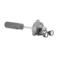
The Series 6900 Cantilever Level Control is designed for use in liquid
level and interface liquid control applications. They are commonly
used in oil and gas processing, manufacturing plants, hazardous
waste disposal, food processing, water treatment, petrochemical
facilities or wherever fluid levels need to be controlled. The unit is
available in either Snap-Acting or Throttling configuration, controlling
pneumatic pressure for various control devices. The standard
displacer is 2” x 10” Delrin and is mounted in a horizontal
configuration. Displacers of other materials and dimensions, as well
as Vertical Displacers are optionally available.
This liquid level control operates based on two physical laws:
-
Archimedes’Principle
A Cantilever beam (sensing rod) projecting outward, anchored at
one end, will flex in proportion ot the weight applied, or removed, at
the free end.
Therefore, following Archimedes Principle, a body (displacer or float)
immersed in a fluid experiences a bouyant, or lift force equal to the
weight of the displaced fluid. This static lift force acts vertically
through the center of gravity of the displaced volume (Figure 1).
Applying the above fundamentals to this liquid level control, we can
sense and regulate levels of most gas-to-fluid interface applications
as well as many fluid- to-fluid interfaces.
Principleof Operation
w
w
“A solid, heavier than a fluid [such as a displacer] will descend to
the bottom of the fluid, and the solid will, when weighed in the fluid,
be lighter than its true weight by the weight of the fluid displaced.”
Note: This document is to be used in conjunction
with WellMark Catalog Document, Section No.
3.5, “Series 6900 Cantilever Liquid Level Control”.
Installation, Operation & Maintenance Instructions
for Series 6900 Cantilever Liquid Level Control
H
1
Weight
H
1
H
2
Weight
Bouyant
Force
Fluid level
rises
Figure 1
(Deflection exaggerated for clarification)