4
1. Select the shelf tray with the uninterrupted flat surface (part 1) and place it upside down on a flat work surface.
2. Turn the push handle (part 3) upside down with the cup holder towards the shelf tray. Using a rubber mal-
let, tap the push handle down into the grooves on the tray. Make sure the handle is all the way on the shelf tray.
HINT: To overcome the friction between the two plastic surfaces, rub a little petroleum jelly onto the grooved
surface. The two parts should slide together with a few gentle taps of the rubber mallet.
3. Since all four legs (parts 5) look alike, positioning of the legs can be confusing. Locate two of the legs, taking
note of the positions of the bottom flanges. Place one nearest the handle (part 3) and the other diagnolly across
the shelf tray corner as shown in the assembly diagram. Using a rubber mallet, tap the legs onto the upper tray
(part 1) until the tab with the three screw holes is in contact with the shelf tray. Repeat this process with the other
two legs so all four legs are in solid contact with the shelf tray.
4. Insert and tighten three screws per leg so that the legs are secured in the shelf tray (part 1). Hint: if needed, rub
some soap on the screw before inserting and tightening it. The soap acts as a lubricant and makes tightening the
screw easier.
5. Now for the lower tray (part 2). Turn the shelf tray upside down and place it onto the four legs (parts 5). The
flanges on the four legs should fit into the depressions in this shelf tray (part 2). If all 12 screws were correctly
secured through the four legs into the shelf tray (part 1), everything should fit together. Gently tap shelf tray (part
2) onto the four legs until the tabs and shelf tray depressions are in contact with each other.
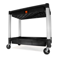
6. Insert the carriage bolts (part 9) up through the leg tabs and the shelf tray (part 2). Attach the casters by first
hand tightening the nuts and bolts. Once all four casters are in place, go back and use an adjustable wrench to
make sure all nuts and bolts are fully tightened and secure.
NOTE: To maximize control, fixed casters are suggested to be put on the same side as the handle (part 3) while
the swivel casters go on the opposite side of the cart. However, if you prefer to have them the opposite way in
order to make sharper turns and pivots, that will also work.
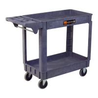
7. Turn the service cart upright and install the towel rack (part 4). Make certain all hardware is tight and that the
casters roll properly before adding any weight onto the cart.
ASSEMBLY
PART DESCRIPTION QUANTITY PART DESCRIPTION QUANTITY
1 Upper Tray 1 7 Swivel Casters 2
2 Lower Tray 1 8 Fixed Casters 2
3 Handle 1 9 Carriage Bolts 16
4 Towel Rack 4 10 Washers 16
5 Legs 4 11 Nuts 16
6 Screws 12
 Loading...