WARNING:
ALL USERS OF THIS EQUIPMENT MUST READ AND
UNDERSTAND ALL INSTRUCTIONS. FAILURE TO DO SO MAY
RESULT IN SERIOUS INJURY OR DEATH. USERS SHOULD BE
FAMILIAR WITH PERTINENT REGULATIONS GOVERNING THIS
EQUIPMENT. ALL USERS OF THIS PRODUCT MUST BE PROPERLY
INSTRUCTED ON HOW TO USE THE DEVICE. AVOID CONTACT
WITH PHYSICAL HAZARDS (THERMAL, CHEMICAL, ELECTRICAL,
ETC.). MAKE ONLY COMPATIBLE CONNECTIONS.
EN 795:2012 Type B CE 2777
Compliance: OSHA 1926.502 & 1910.66
DO NOT REMOVE
Stainless Steel, Aluminum, Zinc Plated Copper,
drill .75 inch Ø
(A) inches
min from any edge
(B) inches
TAP!!!
DO NOT REMOVE
WARNING LABEL!
May be used as an anchor point for a leading edge
restraint system. See optional anchor points below for
example. The use of two anchors is not required for
leading edge restraint systems unless otherwise
specied by the manufacturer.
WORK SURFACE
OPTIONAL
(ANCHOR POINTS)
WORK SURFACE
(ANCHOR POINT)
Concrete must be
3000-psi or higher and
fully cured. Installation
location to be approved
by a qualied person.
MINIMUM CLEARANCE 2 feet (.6m)
DECK/FLOOR/GROUND LEVEL
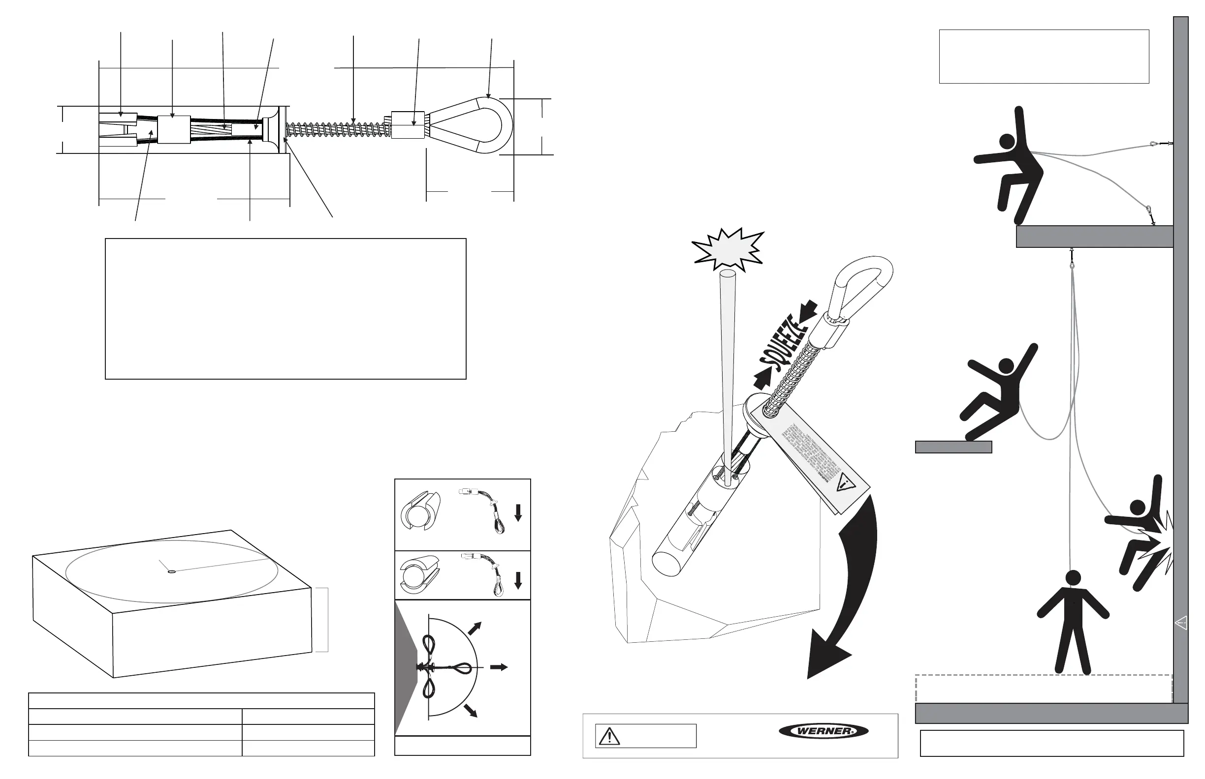
WARNING!!! SWING FALLS MAY OCCUR WHEN THE WORKER IS NOT DIRECTLY UNDER ANCHOR POINT.
All products subjected to fall arresting forces should be removed
from service immediately!
1.25 inches
(31mm)
Cleaning Bushing
5 inches
(127mm)
End Termination
Stop Sleeve
11.5 inches
(293mm)
Heavy Duty Return Wire
Spring
Trigger
Anchor Loop
3 inches
(76mm)
2 inches
(50.8mm)
Spoon
Main Cable
DRILLING & INSTALLATION INSTRUCTIONS:
1. Drill a .75 inch (20mm) diameter hole at least 3.5 inches (89mm) deep. The drilled hole must be straight and
perpendicular to the surface. Make sure the hole is of uniform diameter and free of peaks and valleys on the
inner wall.
2. Blow hole clean with compressed air.
3. Always inspect the hole carefully when reusing a previously drilled hole.
4. When placing anchor, place your thumb inside the anchor loop and your rst two ngers around the trigger.
Squeeze ngers and thumb together till the trigger and spring fully compress.
5. Insert unit at least 3 inches (76mm) deep into hole and release the trigger. Do not force.
6. Set the unit with a slight tug on the anchor loop.
REMOVAL INSTRUCTIONS:
1. When removing anchor, place your thumb inside the anchor loop
and your rst two ngers around the trigger. Squeeze ngers and
thumb together until the trigger and spring fully compress.
2. While squeezing the trigger, pull the anchor out of the hole.
3. If the anchor becomes stuck, insert a punch, screwdriver or other
object into the hole until it touches the top of the cleaning bushing.
4. Lightly tap with a hammer, making sure the tool is touching the top
of the cleaning bushing, while squeezing the trigger. The cleaning
bushing should be easily visible at the edge of the hole.
5. If tool was required to remove the anchorage, inspect thoroughly
for damage after removal. If damage is found, remove from service
and destroy immediately.
Swage
*The user must be equipped with
a means of limiting the maximum
dynamic forces exerted on the
user during the arrest of a fall to a
maximum of 8 kN (1800-lbf). In the
EU these forces must be limited
to 6 kN (1350-lbf).
Stainless Steel, Aluminum, Zinc Plated Copper, 7x19 Aircraft Cable
Pat# US 7,357,363 / 7,011,281 / 6,729,821
Compliance: OSHA 1926.502 & 1910.140 / ANSI Z359.18 Type A, ANSI Z359.7(19)
EN 795:2012 Type B CE 2777
DO NOT REMOVE
P/N 109811-02 REV F 4/21
Reusable Concrete Anchor
Model: A510000
Batch #: XXXX
MFD: MM/YYYY
Minimum Breaking
Strength (MBS): 5000-lbf
INSPECT BEFORE USE
1(888) 523-3371
WARNING:
ALLUSERSOFTHISEQUIPMENT MUSTREAD AND
UNDERSTANDALL INSTRUCTIONS.FAILURE TO DO SO MAY
RESULTINSERIOUS INJURY OR DEATH. USERSSHOULD BE
FAMILIAR WITH PERTINENT REGULATIONSGOVERNING THIS
EQUIPMENT. ALL USERSOFTHISPRODUCT MUST BE PROPERLY
INSTRUCTED ON HOWTOUSE THEDEVICE. AVOIDCONTACT
WITH PHYSICAL HAZARDS(THERMAL,CHEMICAL, ELECTRICAL,
ETC.). MAKE ONLY COMPATIBLE CONNECTIONS.
HOLE DRILLING REQUIREMENT CHART
6 inches (15.3 cm)
12 inches (30.5 cm)
12 inches (30.5 cm)
5 inches (12.7 cm)
PERFORMANCE:
Minimum Breaking Strength (MBS):
5000-lbf (22kN)
Maximum Capacity: One worker when
used as a single point anchorage
connector for personal fall arrest or
restraint system.
DIMENSIONS:
Weight: .44-lbs (200g)
Length: 11.5 inches (293mm)
Diameter .75 inch (19mm)
REGULATORY COMPLIANCE:
ANSI Z359.18 Type A, ANSI Z359.7-2019
OSHA 29 CFR 1926.502, OSHA 29 CFR
1910.140, EN 795:2012 Type B CE 2777
COMPONENT MATERIALS:
Aluminum: Trigger
Aircraft Cable: Main Cable, Activator Wire
Polyurethane: Loop Cover
Stainless Steel: Cone, Spoons, Stop Sleeve
Zinc Plated Steel: Spring
Zinc Plated Copper: Swage
90º
90º
0º
PROPER LOADING
Good
Best
See Spoon Orientation
Good
See Spoon Orientation
*Best practice for spoon orientation
when loaded 90º to hole.
SPOON ORIENTATION
Best
Ok
Load
Load
=
=
(A) Inches Minimum distance from edge/corner (B) Inches Concrete thickness
 Loading...