EasyManua.ls Logo

Wessex VMOP 3045M - User Manual

Wessex VMOP 3045M
4 pages
Print Icon
To Next Page IconTo Next Page
Loading...
Wessex Lift Company Limited
Darren Windibank
Phone: 0044(0) 1794 830303
Fax: 0044(0) 1794 512621
Email: darren.windibank@wessexlifts.co.uk
Page 1 of 4
Technical Bulletin
In addition to our current range of VM Homelift call station options, we are now offering a Wireless
Call Station Option for the UK market. Wireless call stations can be fitted in place of, or alongside,
hard-wired call stations. These will be available for despatch from July 22
nd
.
Below are the Wessex part numbers. Subsequent pages provide installation, set-up, testing, operation
and maintenance detail. Electrical connection detail and dip switch settings are also provided on
drawing VM30 8105 VM Schematic Wiring Diagram.
Part Numbers
Part No. Description
VMOP 3045M Wireless Call Stations Option
This option is made up of the following:
Part No. Description Quantity
EC14 0018 Wireless Call Station Kit 1
VM30 8079 Loom Call Station Wireless 2
VM10 1608 90 Bracket Handset Fixing 2
Please note the Wireless Call Station Kit includes:
Two handsets (with three AAA batteries fitted to each)
One receiver with attached loom
Additional Wireless Handsets are also available.
Part No. Description Quantity
VMOP 1111NM Additional Wireless Handset 1
Documentation
The following relevant documentation has been up-issued:
VM30 8105 VM Schematic Wiring Diagram (now issue D)
VM00 7105 Wessex Homelift User Manual (now issue C)
VM01 5121 UK Technical Sales Specification (now issue D)
From:
Darren Windibank
To:
Wessex UK Agents, Installations, Service
Cc:
CP, PH, DJ, KA, TP, SF, MJ, SP
Date:
13
th
June 2013
Subject:
VM Wireless Call Stations
Bulletin Reference:
Wireless_13062013_1
Question and Answer IconNeed help?

Do you have a question about the Wessex VMOP 3045M and is the answer not in the manual?

Summary

The Wireless Call Station Handset

Battery Replacement

Procedure for replacing the three AAA batteries in each wireless call station handset.

Receiver Installation

Wireless Call Station Looms

Set-up

Dip Switch Settings

Details on configuring dip switches SW3 and SW4 for stop button and door lock solenoid.

Adding a Handset

Adding a Handset

Step-by-step instructions for pairing a new handset to an existing wireless call station system.

Test Procedure

Test Procedure

Steps to verify the functionality of all buttons on the wireless call station handsets.

Checks in the event of a problem

Troubleshooting Common Issues

Steps to diagnose and resolve problems like low battery, no LED illumination, or connection errors.

Overview

This document describes the Wessex Lift Company Limited Wireless Call Station Option, a system designed to provide wireless control for VM Homelift models. It allows for the installation of wireless call stations either in place of or alongside traditional hard-wired call stations, offering greater flexibility in lift control.

Function Description

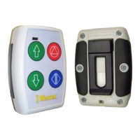
The core function of this system is to enable wireless operation of Wessex VM Homelifts. It comprises wireless call station handsets and a receiver unit. Users interact with the lift using the handset, which transmits commands wirelessly to the receiver, which then controls the lift's movement and door functions. The system supports both up and down movement, stopping the lift, and controlling the door (manual or powered).

Important Technical Specifications

  • Components: The primary components of the Wireless Call Station Option (VMOP 3045M) include:
    • 1x Wireless Call Station Kit (EC14 0018): This kit contains two handsets, three AAA batteries (fitted to each handset), and one receiver with an attached loom.
    • 2x Loom Call Station Wireless (VM30 8079): These are 15-way Molex shorting plugs that replace the 'stop' circuit of hard-wired call station looms.
    • 2x Bracket Handset Fixing (VM10 1608 90): These brackets are used to mount the handsets to a wall.
  • Handset Power: Each wireless call station handset requires three AAA batteries.
  • Wireless Range: The estimated range of the handset within buildings is 20 to 40 metres.
  • Compatibility: The system is designed for all VM Homelift models and door types.
  • Electrical Connections: The receiver loom connects to the PLK on the main PCB. The wireless call station looms connect to the two call station sockets on the right-hand side of the PSU PCB. A 24V DC supply is required on the Red wire (pin 8) of the receiver loom at PLK.
  • Dip Switch Settings:
    • SW3 A (Main PCB): Must be in the lower position to enable the stop button on wireless handsets.
    • SW4 A (Main PCB): Must be in the upper position for both manual and power doors, enabling the door lock solenoid to release.

Usage Features

  • Flexibility: Wireless call stations can be installed instead of or in addition to hard-wired call stations.
  • Portability: Handsets can be unclipped from their wall brackets and used as portable devices. However, for safety, it is recommended to keep the handset on its wall bracket while the lift is in use.
  • User Interface: Each handset features:
    • Green LED & Red LED (Green illuminates when a button is pressed; Red flashes for 5 seconds when batteries are low).
    • Up Direction Button.
    • Down Direction Button.
    • Stop Button.
    • Manual Door Lock Release Button or Powered Door Open/Close Button (depending on door type).
  • Adding Handsets: Additional wireless handsets (VMOP 1111NM) can be easily added to an existing system. The process involves holding a magnet over a specific area of the receiver, waiting for a short bleep, pressing the Up arrow button on the new handset, and then waiting for two long bleeps to confirm successful pairing.
  • Safety Recommendation: Key switches are not available on wireless call stations. If key switch functionality is required, the hard-wired call station option is recommended. To prevent unauthorized use, users can place an unclipped handset in a secure location.

Maintenance Features

  • Battery Replacement: The three AAA batteries in each handset should be replaced annually by a service provider or competent person. Replacement involves removing six screws from the rear of the handset, then two screws from the battery holder. Care must be taken not to pinch wires during reassembly.
  • Troubleshooting (Checks in the event of a problem):
    • Low Battery Indication: A flashing Red LED on the handset after a button press indicates low batteries, prompting replacement of AAA batteries.
    • Green LED Check: If the Green LED does not illuminate when a button is pressed, check the AAA batteries.
    • Dip Switch Verification: Ensure dip switches SW3 A and SW4 A on the main PCB are correctly set according to the specifications (refer to drawing VM30 8105).
    • Wiring and Connection Checks:
      • Verify correct wiring and connection of Wireless Call Station Looms, ensuring the link wire connects from pin 1 to pin 4.
      • Confirm correct wiring of the receiver loom to PLK (refer to drawing VM30 8105).
      • Check for 24V DC on the Red wire (pin 8) of the receiver loom at PLK.
      • If all previous checks are sound, inspect all wiring to the receiver PCB. This involves removing the receiver, unscrewing and removing the antenna, removing two screws from the base of the receiver casing, and sliding out the receiver PCB for inspection.
  • Documentation: Relevant documentation, including the VM Schematic Wiring Diagram (VM30 8105), Wessex Homelift User Manual (VM00 7105), and UK Technical Sales Specification (VM01 5121), has been updated to reflect the wireless call station option.

Wessex VMOP 3045M Specifications

General IconGeneral
BrandWessex
ModelVMOP 3045M
CategoryController
LanguageEnglish