INSTRUCTIONS
FOR
WESTON
MODEL 686 - TYPE lOA
True Mutual Conductance Vacuum
Tube Analyzer
CONTENTS PAGE
Controls, Variable
Control Grid Voltage AdjusteL_mmm m_umm_m4
Heater Voltage Adjusterm_uhm_mmum_m__uu__m___A
Hum mmmmm_u__u__um___m__umm 5, 7 (Step27)
Plate Voltage Adjuster:
See "D-C Power Supply Controls"mm u m_5
Screen Voltage Adjuster:
See "D-C Power Supply Controls"m_mmm__m_m5
Self- Bias Resistance
00 ___ _ 00 _00 __ __ m __ _ __ __ _ _ _ _00 __ _m___5
Signal Amplitude AdjusteL_m__uuuum_5, 8 (Step 29)
Suppressor Voltage Adjuster:-
See "D-C Power Supply Controls"m__m__m__mu__5
D-C Power Supply Controls_m_m_mmmmm m__5
Detailed Description of Model 686 Type 10A__3-4-5-6
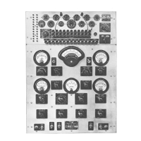
Front Panel View of Model 686 Type 10Am_mmmm__2
General Description m m___n__m_m mm_3
General Information __nm__mm__h__mum_mm_mmmm_
10
Gm Readings
Amplifier Tubes __hu mm___mm__u__mnm__mm_m7-8
Inconsistent on Filament Types:
See "Hum Control" _mm___mmm_mmu5, 7 (Step 27)
Low Gm Indications_muum__mumumm___m_m_hu 11
No G.m Indications_mm_m_mmmmm__mmmummuu 11
Grid Current _mmmm m_m_mm_m3, 7 (Step 28), 10
Helpful Suggestions in Tube Testinguhuum__h_uhum_1 0
Instruction Book um_mm_m__m m_m m h 10
Maintenance uhm_m m_m_m_mum_m_h__mmum
11
Meters
Control Grid Voltageu n__n mn_m__n nu4
Element Current _m m_m__m___m__mm m4
Element Voltage u umu__m mm 4
Gm (Mutual Conductance} m uu m___3
Grid Current __ 00__m__ um m__m ________00_3
Heater Voltage mmmmm_m_mmm m_mm__mm_h__4
Operation
Line Connections for 230 Voltsm___un__m__m_m m_6
Step-By Step Test Procedure__um__mm_un_m6-7-8-9
Theory of Operation_m_mm_m mumumm_ 9-10
*
CONTENTS
PAGE
Order of Adjustment of Element Potentiometersmmm_5
Ordering Information _u__mm__mm mmm__m__m
11
Precautions __u__h__mm_mm_m_h mm_mm_umm m 11
Switches, Rotary
"Control Grid" (bias} mmm m_m___m_m_-4
"Heater Voltage" u__m__mm__mm_m_nnm__m_mm_mA
"Gm Ra nge" _00 0000000000
3
"Element Current" mm mnm__m_m_mmmm__m_m__A
"Element Current Range"m__m__mmmmmmmm_m_A
"Element Voltage" ummm_mm mm_m_m_m__mu4
"Element Voltage Rang,e" __mmmmm hum_m___mA
Switches, Toggle
"Gm Reading" __nm um m_m m__m 6
"H eater Supply" 00 0000 0000___000000
6
"Gm Factor" n nn ~ 3
" Lamp Test' 00 00 000000___ ___00 000000 6
"Microamperes" u__m_uum m__mm_m__umm 3
"Plate 1 - Plate 2" uu__mm_mmm__mn m__um___uu5
"Plate Su pply" nu m__m m m6
"Signal Cal." 00000000 00 000000 0000 00___6
"Supp" (Pos-Neg) mmm umm umm__6
Tube Manuals m_m_mmnmm__m_m__m mmmmm
10
Tube Reject Limits mm mum mu m__n m___m_ 10
Tube Testing
Ampl ifiers
_____u__m_mu 00_m__ ___u_m__ umu_ _____um _6-7-8
Converters & Mixer Oscillatorsm_mm__m_h mm__8
Diode Detectors ___mnum_m___m m m_mm8
Rectifie rs _ _ ___ __ _ _ __ 00_ _ _ ___ _ __ _ __ _ _ ___ _ __ ___ __ _ _ _ ___ 00 __ _ _00 __ _ 00 8
Thyratro n s __ __ _ __ _ _ ____ _ _ __ _ _ _ ___ _ __ __ _ __ __ _ __ _ _ ____ _ __ _ _ _ - - - - - - - - - - - - 8-9
Voltage Regulators hu__mm__mmuu nmm_mm__mn9 '
Wiring Diagram of Model 686 Type 1OAu__m_humm12
I
 Loading...