08
OPERATION
MENU
09
OPERATION
MENU
5 Wiring and Terminal5 Wiring and Terminal
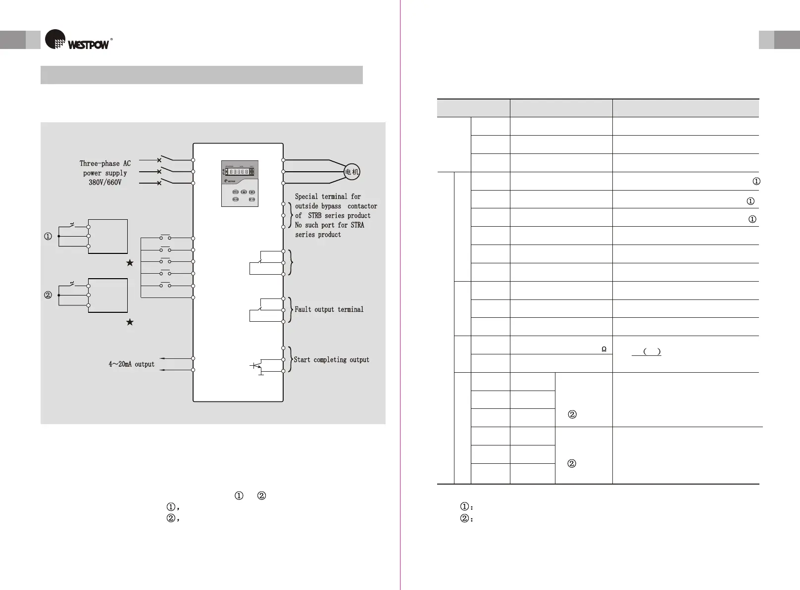
5.1 Wiring schematic5.1 Wiring schematic
JOG
RET
COM
U
V
W
W1
U1
V1
K24
K21
K22
K14
K11
K12
+12V
OC
COM
R
S
T
QF
RUN
STOP
SS
I
COM
K
K
RUN
STOP
COM
RUN
SS
COM
two line controltwo line control
I
KeyboardKeyboard
Control terminal for bypass
contactor
Control terminal for bypass
contactor
two line controltwo line control
Figure 5-1
Note:
1. There are two wiring ways to control the soft starter to start and stop.
They are three-line and two-line wiring. ( See and in the figure above ).
Connect according the figure free stop
Connect according the figure soft stop
2. In the A series product, there is no terminals U1,V1,W1. Because there is inner
bypass contactor.
5.2 External Terminals Explain5.2 External Terminals Explain
Terminal NameTerminal Name
R.S.TR.S.T
bypassbypass
U.V.WU.V.W
inputinput
U1.V1.W1U1.V1.W1
output output
see figure F-6see figure F-6
Main
circuit
Main
circuit
start the motorstart the motor
RUNRUN
stop the motorstop the motor
STOPSTOP
jog the motorjog the motor
JOGJOG
reset the faultreset the fault
RETRET
CommonCommon
COMCOM
Inner powerInner power
+12V+12V
Start completeStart complete
OCOC
COMCOM
II
COMCOM
K14K14
K11K11
K12K12
NONO
K24K24
K21K21
K22K22
SSSS
soft stopsoft stop
Table 5-1
Terminal functionTerminal function
ExplanationExplanation
connect to three-phase power source
through breaker (QF)
connect to three-phase power source
through breaker (QF)
connect to three-phase asynchronous
motor
connect to three-phase asynchronous
motor
Digital inputDigital input
Digital outputDigital output
Analog
output
Analog
output
Relay outputRelay output
Control circuitControl circuit
commoncommon
4-20mA output
load input resistance<400
4-20mA output
load input resistance<400
4-20mA output reference4-20mA output reference
NCNC
COMCOM
NONO
NCNC
COMCOM
fault
output ter
minals
fault
output ter
minals
bypass
terminals
bypass
terminals
connect SS and COM directly, soft stop connect SS and COM directly, soft stop
connect RUN and COM directly, start connect RUN and COM directly, start
connect STOP and COM directly, stop connect STOP and COM directly, stop
connect RET and COM directly,
reset the fault
connect RET and COM directly,
reset the fault
logic groundlogic ground
connect JOG and COM directly, jogconnect JOG and COM directly, jog
Inner power: DC12V,100mAInner power: DC12V,100mA
OC is on after start completedOC is on after start completed
Inner power referenceInner power reference
Im:motor output current(A)
Ie:motor rate current(A)
I: 4-20mA output current(A)
Im:motor output current(A)
Ie:motor rate current(A)
I: 4-20mA output current(A)
Im= Im=
Ie I-4Ie I-4
88
In Fault K14-K12 close
K11-K12 open
contacts capacity AC:10A/250V
DC:10A/30V
In Fault K14-K12 close
K11-K12 open
contacts capacity AC:10A/250V
DC:10A/30V
after start complete K24-K22 close
K21-K22 open
contacts capacity AC:10A/250V
DC:10A/30V
after start complete K24-K22 close
K21-K22 open
contacts capacity AC:10A/250V
DC:10A/30V
Note There are two connecting mode, see figure 5-1
Note Fault and bypass output terminals are all dry contact.
Note There are two connecting mode, see figure 5-1
Note Fault and bypass output terminals are all dry contact.
User ManualUser Manual User ManualUser Manual
 Loading...