P82055 S
Sheet 2 of 4
WARNING: THE SPEAKER APPLIANCES MUST BE FIELD SET TO THE DESIRED dBA SOUND OUTPUT
LEVEL BEFORE THEY ARE INSTALLED. THIS IS DONE BY PROPERLY INSERTING JUMPER PLUGS IN
ACCORDANCE WITH THESE INSTRUCTIONS. INCORRECT SETTINGS WILL RESULT IN IMPROPER
PERFORMANCE, WHICH COULD RESULT IN PROPERTY DAMAGE AND SERIOUS INJURY OR DEATH TO YOU
AND/OR OTHERS.
Each letter corresponds to a plug position of the header located on the printed circuit board. Select voltage and wattage as shown in
Table 2 below.
Table 2: Speaker Voltage and Wattage Connection Chart
Input 1/8 1/4 1/2 1 2 4 8
25.0VRMS E D C J B - A
70.7VRMS F G H E D C J
GROUNDING: Connect ground wire to backbox. Install signaling appliance to backbox using mounting screws provided.
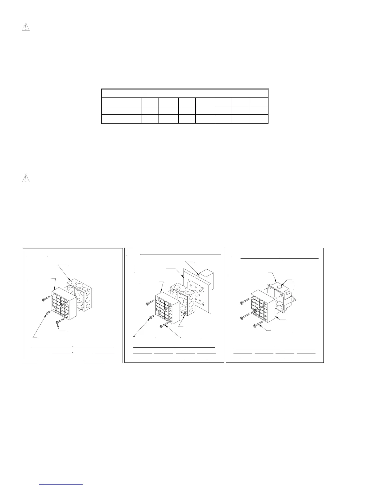
MOUNTING OPTIONS:
CAUTION: The following figures show the maximum number of field wires (conductors) that can enter the backbox used with
each mounting option. If these limits are exceeded, there may be insufficient space in the backbox to accommodate the field wires
and stresses from the wires could damage the product.
Although the limits shown for each mounting option comply with the National Electrical Code (NEC), Wheelock recommends use
of the largest backbox option shown and the use of approved stranded field wires, whenever possible, to provide additional wiring
room for easy installation and minimum stress on the product from wiring.
MAXIMUM NUMBER OF CONDUCTORS
AWG #18 AWG #16 AWG #14 AWG #12
4 4 44
DEEP BACKBOX
#8-32 SCREWS
SURFACE MOUNTING
A
SPEAKER
#10-32 SCREWS
CONCEALED CONDUIT MOUNTING
MAXIMUM NUMBER OF CONDUCTORS
AWG #18 AWG #16 AWG #14 AWG #12
4 4 44
EXISTING BOX
IN WALL
ADAPTOR PLATE WITH
#8-32 & #6-32
SCREWS & BUSHING
B
(2) #8-32 SCREWS
(2) #10-32 SCREWS
WITH #8-32 SCREWS
DEEP BACKBOX
SPEAKER
WEATHER RESISTANT MOUNTING
MAXIMUM NUMBER OF CONDUCTORS
AWG #18 AWG #16 AWG #14 AWG #12
4 4 44
#8-32 SCREWS
C
1/2" CONDUIT
ENTRANCE
WEATHER RESISTANT
BACKBOX
ON TOP
SPEAKER
ET-1010 can be Ceiling or Wall Mounted
 Loading...