TECH SHEET - DO NOT DISCARD PAGE 2
FOR SERVICE TECHNICIAN'S USE ONLY PART NO. 3979119
Fabric Care/Temperature
Switch Test
Remove the wires
from the switch to
complete this test.
Reference contact
continuity with Pins
1 and 2 to Pin 4.
Reference contact
continuity with Pin 3 to Pin 5.
Fabric Care Switch Test
SWITCH
POSITION
CONTACTS
FUNCTION
321
9 O’clock O O O NO HEAT
10 O’clock O O X EXTRA LOW
12 O’clock O X O MEDIUM
2 O’clock O X X MEDIUM HIGH
3 O’clock X O O HIGH
O = OPEN X = CLOSED
Wrinkle Guard Switch (On/Off)
Test
Remove the wires
from the switch to
complete this test.
Reference contact
continuity to
Pin 4 (White).
Wrinkle Guard Switch Table
SWITCH
POSITION
CONTACTS FUNCTION
11 O’clock Open Wrinkle Guard OFF
1 O’clock Closed Wrinkle Guard ON
“End of Cycle” Signal Switch
Test
Remove the wires
from the switch to
complete this test.
Reference contact
continuity to
Pin 4 (White).
Signal Switch Table
SWITCH
POSITION
CONTACTS
FUNCTION
12
10 O’clock O O OFF
12 O’clock X O
LOW End
of Cycle Signal
2 O’clock O X
HIGH End
of Cycle Signal
O = OPEN X = CLOSED
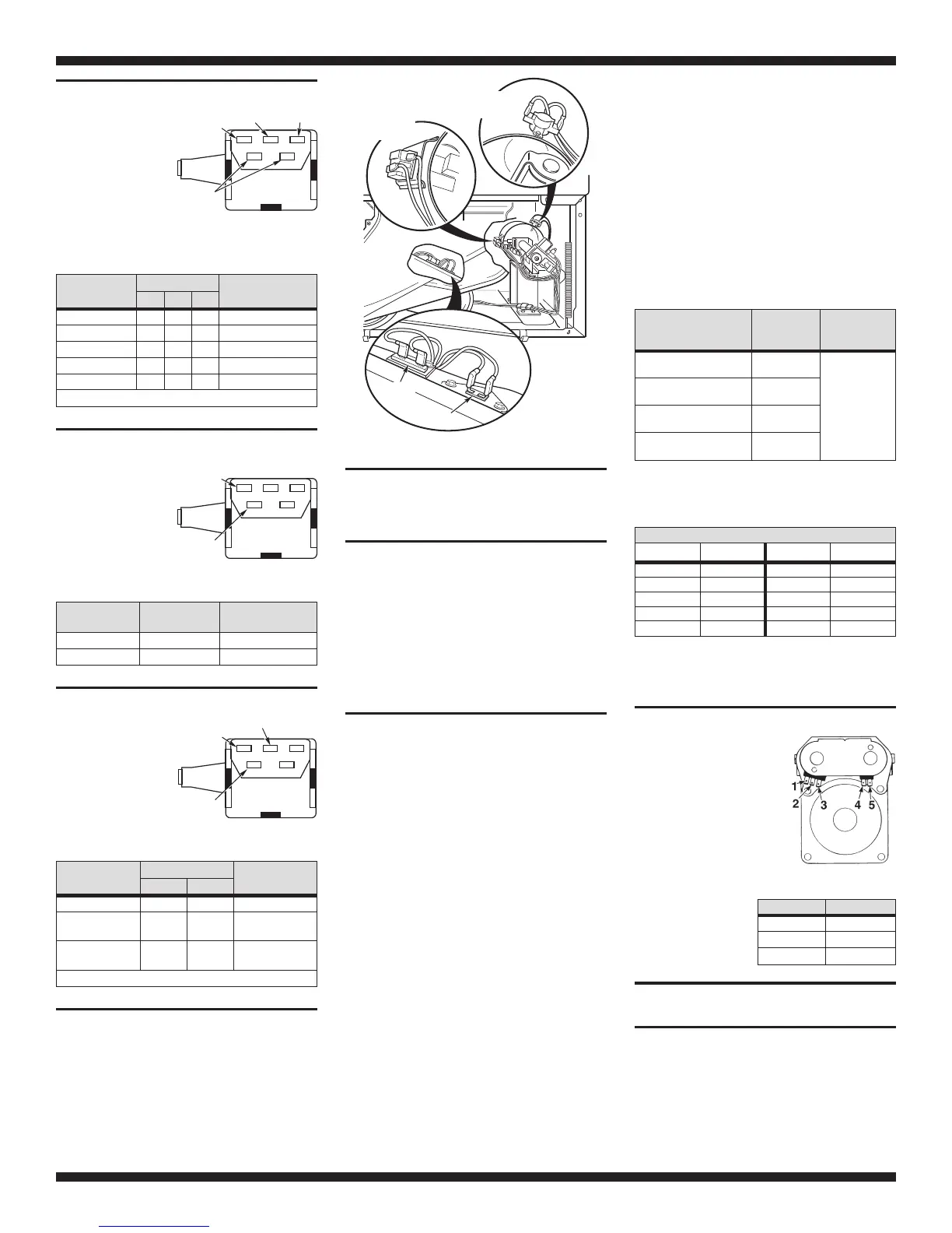
Heater Box High-Limit
Thermostat Test
Remove the thermistor from the fan housing
and plug the hole. Protect the thermistor and
leads from grounding against any metal parts.
See Figure 1. Completely block the exhaust
outlet. Turn dryer on and allow the high-limit
thermostat to cycle once, then measure the
time elapsed until the high-limit thermostat
trips. It should trip between 21 and 38 seconds.
IMPORTANT: Be sure to reinstall the thermis
-
tor after testing thermostat.
Thermal Fuse Test
A thermal fuse is used on this model. The ther-
mal fuse is wired in series with the dryer gas
valve. If the thermal fuse opens, power is shut
off to the gas valve. (Centrifugal switch in mo-
tor also opens heater circuit.)
Once the thermal fuse has opened, it must be
replaced. Check for failed thermistor or other
cause of failure. Replace failed parts. See
Figure 1.
Thermistor Test or Dryer
Beeps 3 Times When Push To
Start (PTS) Pressed
An electronic temperature sensor called a
thermistor is used in this model in place of an
operating thermostat. The Even Heat Control
monitors the exhaust temperature using the
thermistor and cycles the heater relay on and
off to maintain the desired temperature.
Procedure
Begin with an empty dryer and a clean lint
screen.
1. Set the following configuration:
■
Timer Dial - TIMED DRY
■
Fabric Care/Temperature switch -
COTTON / TOWELS HIGH
■
Wrinkle Guard switch - OFF
■
Signal switch - HIGH
■
Door - must be closed
2. Press the Push To Start (PTS) switch.
a. If you hear three short beeps and the
dryer shuts off after several seconds, the
thermistor or wire harness is either
shorted or open. Check wire connec
-
tions at Even Heat Control and thermis
-
tor. If wiring is functional, replace the
thermistor: Unplug the dryer and remove
the front toe panel. Remove the two
wires and replace the thermistor as
shown in Figure 1.
b. If the dryer appears to operate correctly,
proceed to step 3.
3. Remove exhaust vent and start the dryer.
a. Turn Fabric Care/Temperature switch to
desired temperature to be tested, and
select 20 minutes on the Timed Dry dial.
Hold a glass bulb thermometer capable of
reading from 90°F to 180°F in the center of
the exhaust outlet. Measure exhaust tem
-
peratures with heater off and on. The
correct exhaust temperatures are as
follows:
FABRIC CARE/
TEMP. SWITCH
SETTING
HEAT
TURNS
OFF
HEAT
TURNS
ON
COTTON / TOWELS
HIGH
150° ± 10°F
10° - 15°F
below heat off
NORMAL
MEDIUM HIGH
140° ± 10°F
PERM PRESS / CASUAL
MEDIUM
125° ± 10°F
ULTRA DELICATE
EXTRA LOW
115° ± 10°F
b. If the exhaust temperature is not within
specified limits, check the resistance of
the thermistor.
THERMISTOR RESISTANCE
TEMP. ° F RES. K Ω TEMP. ° F RES. K Ω
50° 19.9 100° 5.7
60° 15.3 110° 4.7
70° 11.9 120° 3.7
80° 9.2 130° 3.1
90° 7.4 140° 2.5
c. If the thermistor resistance checks within
normal limits, replace the Even Heat
Control Assembly.
Gas Valve Test
Using an ohmmeter, it is
possible to determine if
either gas valve coil has
failed. Remove harness
plugs. Measure resis-
tance across terminals
indicated in the chart
below. Readings should
match those shown in
chart. If not, replace coil.
IMPORTANT:
Be sure all harness
wires are looped
back through the
strain relief after
checking or
replacing coils.
TROUBLESHOOTING
PROBLEM: Dryer Will Not Run
(Refer to Motor Strip Circuit, page 6)
If the motor will not start, check the following:
– LINE VOLTAGE
– HARNESS/CONNECTION
– MOTOR RELAY
– PUSH TO START (PTS) SWITCH
12
White/Black
SIGNAL
White
Tan
White
4
123
Orange
FABRIC
White
Violet Tan
45
Thermistor
Flame
Sensor
Thermal
Fuse
High Limit
Thermostat
Figure 1
1
Gray
WRINKLE
GUARD
White
4
TERMINALS RESISTANCE
1 to 2 1365Ω±25
1 to 3 560Ω±25
4 to 5 1220Ω±50
 Loading...