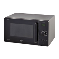
Do you have a question about the Whirlpool GM8155XJB and is the answer not in the manual?
To provide detailed information enabling service technicians to diagnose malfunctions and repair the Microwave-Convection Oven.
Details safety precautions and requirements for grounding the microwave oven.
Specific caution regarding the type of fuse to use for replacement.
Instruction to replace interlock switches and relays with sticking contacts.
Mandatory replacement of interlock switches when a fuse blows.
Check interlock operation, door closing, and seals for safety.
Check door hinges, latches, and look for signs of dropping or abuse.
Safety regarding high voltages, component handling, grounding, and capacitor discharge.
Power disconnect, grounding plug use, and general hazard warnings.
Ensure air vents are clear and follow ESD precautions for electronics.
Detailed steps for conducting the R.F. leakage test on the microwave oven.
Procedure for reporting and handling ovens with excessive RF leakage.
Diagram showing the location of various internal components within the microwave oven.
Remove the glass turntable and roller assembly from the oven cavity.
Locate and remove specific screws securing the microwave oven cabinet.
Gently pull the cabinet back and unhook it to remove.
Remove the screw securing the top of the electronic oven control.
Open the microwave oven door to access the control panel.
Slide the control up, unhook tabs, and pull the unit forward.
Disconnect all wire connectors from the EOC board.
Lift locking ring and remove ribbon cable, then remove screws to detach the board.
Remove three screws and unclip the board from its locking arms.
Disconnect wire connector and pull out the primary switch.
Disconnect wire connector, press locking arm, and rotate switch to remove.
Remove the two screws from the top cover.
Lift the top cover and bend clips to remove the humidity sensor cable.
Disconnect the humidity sensor connector CN4 from the control board.
Remove the mounting screw and slide the sensor out of its slot.
Disconnect wire connector, remove mounting screw, and pull lamp out.
Disconnect wire connector and remove two mounting screws.
Disconnect wire connector and remove mounting screw.
Disconnect wire connectors from the oven thermostat terminals.
Remove the two screws from the damper motor housing.
Pull damper motor housing out and remove the oven thermostat.
Disconnect the filament connector from the magnetron terminals.
Crucial safety step to discharge high voltage capacitor before touching components.
Refer to page 2-2 for the procedure to remove the oven cabinet.
Disconnect power before servicing oven door, actuators, and glass.
Disconnect the electrical power to the microwave oven.
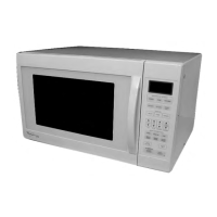
| Capacity | 1.5 cu. ft. |
|---|---|
| Turntable | Yes |
| Color | Black |
| Sensor Cooking | Yes |
| Convection Cooking | No |
| Control Type | Electronic |
