ON/OFF
THRESHOLD HOLD TIME
AUTO
SWITCH
A B
STATUS
CH. 1
SELECT
B
A
M
CH. 2
SELECT
B
A
M
CH. 3
SELECT
B
A
M
CH. 4
SELECT
B
A
M
CH. 5
SELECT
B
A
M
CH. 6
SELECT
B
A
M
CH. 7
SELECT
B
A
M
CH. 8
SELECT
B
A
M
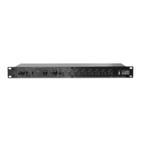
AB-8 8 ch Audio Switcher
POWER
MASTER CONTROLS
AUTO-SWITCH
TRIGGER
MANUAL
U.S.Audio
Auto-switch on/off switch engages the signal sensing circuit to control when the unit switches from A to B with
the loss of signal on channel one A.
Threshold control sets the level at which the signal present on channel one A will keep the A channels
connected to COMMON. When the channel one A signal falls below this threshold, the AB-8 will automatically
switch COMMON channels to the B channels. Only COMMON channels set to the M (Master) position are
switched, COMMON channels set to A or B are not switched automatically. The threshold operates through a
signal range of –40 dB to +20 dB.
Trigger LED illuminates green when the signal level on channel one A is above the threshold level and stays
green until that signal is removed. It then illuminates red through the duration of the hold time.
Hold time control adjusts the length of time before the AB-8 Auto-switches the COMMON channels from A to
B when the channel one A signal falls below the level set by the threshold trim pot.
Auto-switch LED illuminates when the Auto-switch function is engaged.
Manual A - B switches change all channels assigned to the Master Controls with a single push of either
switch.
A - B LEDs indicate whether A or B channels assigned to the Master Controls are connected to the COMMON
channels.
Channel Select switches control the A - B connection to COMMON individually for each channel. Any of the
eight channels can independently connect A or B to COMMON or assign the channel to the Master Controls
for simultaneous multi channel switching.
Channel yellow and red LEDs indicate the current switching status of each individual channel and the green
LED illuminates when the channel is connected to the Master Controls.
Power switch turns the power on to the AB-8. The AB-8 automatically connects A to COMMON on all eight
channels when power is turned off. However, the LEDs will show no indications.
COMMON Female Dsub 25 connector can be either an input or output connection for eight channels of
®
balanced audio. The connector is wired to the Tascam DA88 standard pinout.
B Female Dsub 25 connector can be either an input or output connection for eight channels of balanced audio.
®
The connector is wired to the Tascam DA88 standard pinout.
A Female Dsub 25 connector can be either an input or output connection for eight channels of balanced audio.
®
The connector is wired to the Tascam DA88 standard pinout.
Link In and Out jacks are standard ¼” tip- sleeve and are used for connecting multiple AB-8 units together
under Single Master Control from the first unit in the chain. The Master Control sections and footswitch
controls of all slave units are disconnected. An external control voltage can also be used to activate
switching from A to B. 0 VDC applied to the tip of the LINK IN jack connects A channels to COMMON and +5
VDC on the tip connects B channels to COMMON. Both control voltages are referenced to the sleeve
contact of the jack. In this configuration all Master Controls are deactivated.
Footswitch jack allows Master Manual switching using a standard momentary N.O. footswitch in addition to
the A - B Buttons on the front panel. The jack is ¼” tip- sleeve.
Power IEC inlet connects to incoming AC power with a voltage range of 90- 230 VAC at 50 or 60 Hz.
®
Tascam DA88 is a registered trademark of the TEAC corporation Toyko, Japan
1 2
Controls and Functions
1.
2.
3.
4.
5.
6.
7.
8.
9.
10.
11.
12.
13.
14.
15.
16.
3
4
5
6
7
8 9 10
1112
13
14
1516
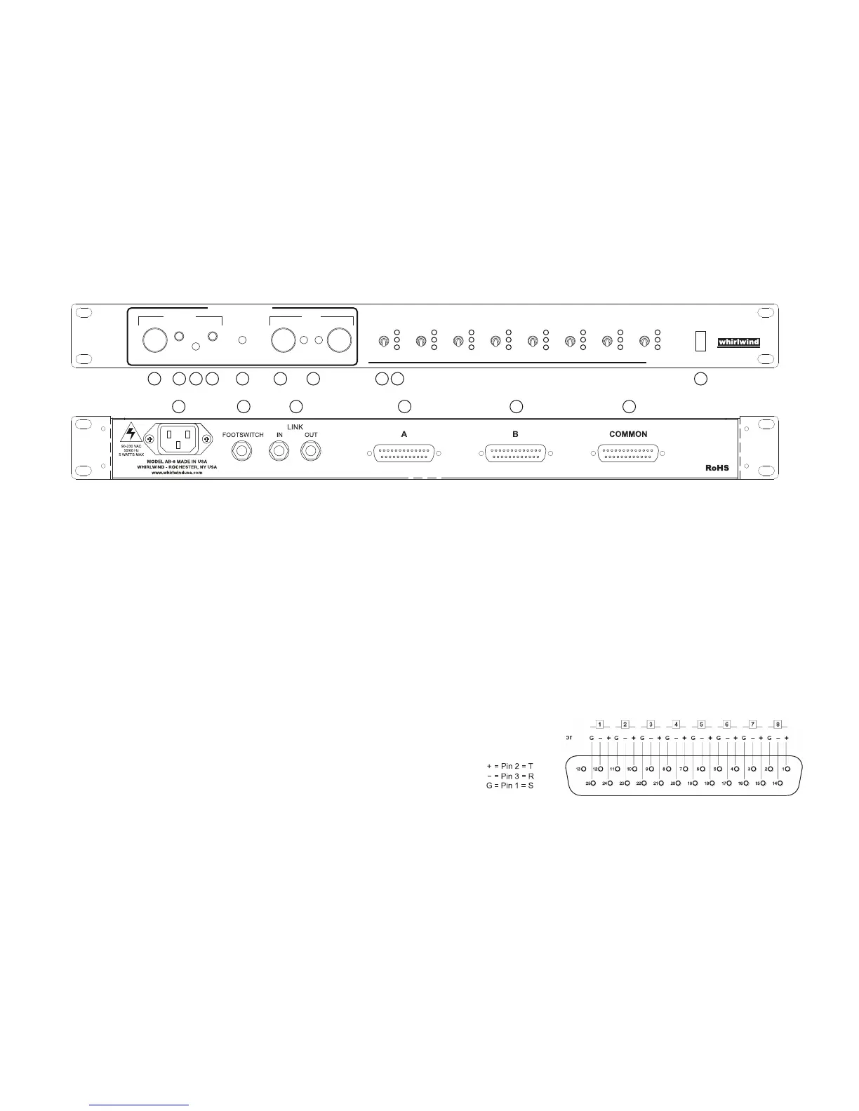
G
-
+
G
-
+
G
-
+
G
-
+
G
-
+
G
-
+
G
-
+
G
-
+
Pin-out for TASCAM DB25
8 Channel Balanced Connector
 Loading...