507LIT LED-PS WI -2
06.05.01
DIGITAL NO-FLOW TIMER
U.S. PAT. NO. 5,835,372
P/N 000507 DNFT-LED-PS DIGITAL NO-FLOW TIMER WITH DEDICATED PROXIMITY SWITCH.
INSTALL ON SWITCH RATING 2.5VA 240VDCDROPSA/LINCOLN/SBCO/LUBRIQUIP DIVIDER BLOCK.
000507
WIRING LEGEND
CAUTION: DISCONNECT ALL WIRING PRIOR TO WELDING ON COMPRESSOR OR SKID.
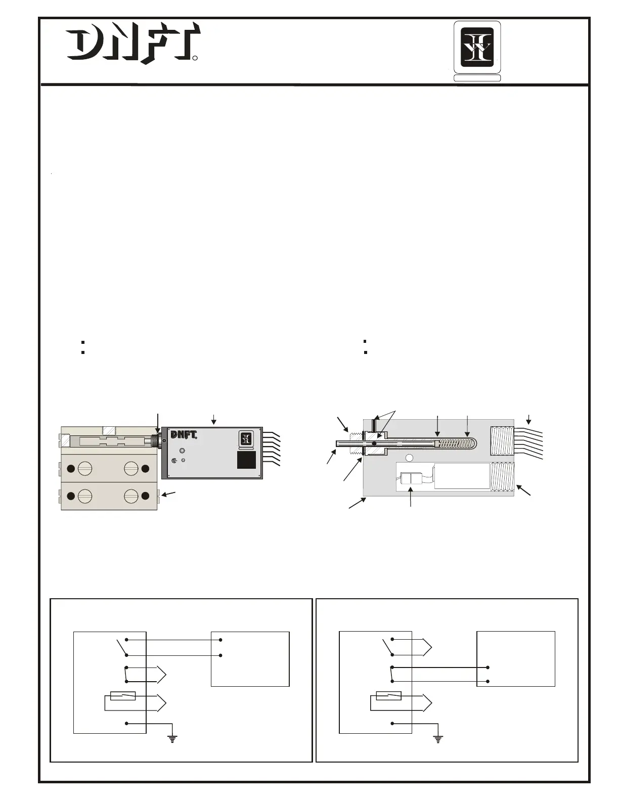
INTERNAL VIEW OF
DIVIDER VALVE
(E)
O-RING OR
METAL GASKET
(F)
24S
PISTON ENCLOSURE PLUG
(D)
24S
DNFT-LED-PS
DIGITAL NO-FLOW TIMER
R
3-MIN
2.5VA / 240VDC
LED-PS
U.S. PAT. NO. 5,835,372
RED-Open Loop ORANGE-Closed Loop
MODEL
RATED
SERIAL #
PN
ALARM
186200
CE
R
USC
Cl I; Div 1; Grps. A,B,C,D;T4
Cl I; Zone 1; Ex md IIC T4
Factory Sealed
CYCLE INDICATION
0344
KEMA 00ATEX1090 X Amb. -40° C...+80°C
II 2G EEx m IIC T5
000507
GRN-GND YEL-PROX. SWI.
RED
ORANGE
ORANGE
RED
GREEN
YELLOW
YELLOW
DNFT
(B)
MAGNET
(H)
POLARIZED CONNECTOR
CONTROL HOUSING
SPRING
SPACER
LED
#22 AWG 18" LEADS (7)
(I)
O-RING
(F)
1/2“ PIPE PLUG
FIELD REPLACEABLE
BATTERY
P/N:000505
MAGNET
HOUSING
(C)
ALLEN HEAD
SET SCREWS(2)
(A)
RED
RED
GREEN
ORANGE
ORANGE
YELLOW
YELLOW
RED
YELLOW PROXIMITY
SWITCH
GREEN GROUND
CONTROL PANEL
ANNUNCIATOR
OR PLC
ORANGE
INSULATE
FROM CONTACT
RED
OPEN LOOP MODE
NOTE: WIRING CONNECTION
FOR UNIT IN OPERATION
YELLOW PROXIMITY
SWITCH
GREEN GROUND
CONTROL PANEL
ANNUNCIATOR
OR PLC
RED INSULATE
FROM CONTACT
ORANGE
ORANGE
CLOSED LOOP MODE
NOTE: WIRING CONNECTION
FOR UNIT IN OPERATION
RED..................NORMALLY OPEN OPERATION
ORANGE..........NORMALLY CLOSED OPERATION
GREEN.............CASE GROUND
YELLOW...........DEDICATED PROX. SWITCH
UNIT MUST BE SECURELY GROUNDED. DISCONNECT
ALLWIRING PRIOR TO WELDING ON SKID.
DNFT-LED-PS
000507
000507
1. Loosen all Allen head set screws (A) on DNFT (B) and remove magnet housing (C). Do not remove magnet, spring or spacer
from magnet housing.
2. Remove piston enclosure plug (D) from end of divider valve where DNFT will be installed. The DNFT does not have to be
installed on the top divider valve. It may be installed on any convenient divider valve, top to bottom. (Notice:Do not install DNFT
on Lincoln divider valves with cycle indicator pins or any Dropsa divider valve less than SMX 16.)
3. Be sure O-ring or metal gasket (F) is in place on magnet housing (C). Screw magnet housing (C) into end of divider valve (E).
Torque to 15 foot pounds max.
4. Slide DNFT (B) all the way onto hex of magnet housing (C). Tighten set screws on hex of magnet housing. Torque 25 inch
pounds max.
5. The LED on the DNFT indicates each divider valve cycle. This enables operator to adjust the lubricator pump for correct cycle
time and oil consumption recommended by compressor manufacturer. If LED does not blink with compressor running or by
manually pumping oil into divider valve, the DNFT must be adjusted. Normal cycle indication is a bright strobe type blink.
6. Before adjusting DNFT, divider valve must be cycling. This can be achieved with the compressor running or by manually
pumping oil through the divider valve assembly with a hand priming pump.
7. Adjustment is made by sliding the DNFT (B) all the way on the hex of the magnet housing (C). Tighten set screws on hex of
the magnet housing to 25 inch pounds max. Check for LED blink to confirm correct adjustment. If LED does not blink with divider
valve cycling, adjust the DNFT back in 1/16" increments. Correct adjustment of the DNFT is confirmed by blinking LED.
8. All conduit and connections should be appropriate for area classification. Notice: Conduit and fittings must be supported to
avoid bending magnet housing.
9. After installing magnet assembly and pre-compressor start-up, it is absolutely necessary to purge all air from divider
block lubrication system. This can easily be accomplished with a lubrication system purge gun.
10.DNFT must be installed with correct magnet assembly for each divider valve manufacturer.
Lincoln-7/16"-20 extended nose with O- ring Dropsa
Trabon-1994 or earlier 7/16"-20 with metal crush gasket SBCO & Trabon-1995 and up 7/16"-20 with O-ring
Notice: When installing more than one DNFT, each DNFT must be wired to a separate alarm circuit
of the control panel, annunciator or PLC to simplify troubleshooting the lubrication system and DNFT.
ODESSA, TX USA
INSTRUMENT
WHITLOCK
1-800-337-3412
www.noflo.com
ODESSA, TX USA
INSTRUMENT
WHITLOCK
1-800-337-3412
www.noflo.com
WHITLOCK INSTRUMENT
1300 N. Texas
Odessa, TX 79761
432.3373412 Fax 432.335.5926
1.800.337.3412 www.noflo.com
 Loading...