The Williams Sound Personal PA/FM Broadcasting System is designed for easy installation and use, even for individuals with minimal electronic experience. It functions as a personal public address and FM broadcasting system, allowing for audio transmission to receivers within a specified range.
Function Description
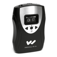
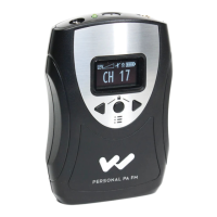
The system consists of a transmitter (Models T4 and T4P) and receivers (Models R7, R7M, R7-4, and R700). The transmitter takes audio input from various sources (line-level or microphones) and broadcasts it via FM radio waves. Receivers then pick up this broadcast, allowing listeners to hear the audio through earphones or an internal loudspeaker (R700). The system is particularly useful for assisting hearing-impaired listeners by providing clear, direct audio.
Important Technical Specifications
Transmitters (Models T4, T4P)
- Physical:
- Dimensions: 6-1/2" W x 2-1/2" H x 6" D
- Weight: 1.6 lbs
- Audio Specifications:
- Inputs:
- Balanced Bridging: 10K Impedance, Female XLR
- Unbalanced: 100K Impedance, RCA Jack
- Input Level: 0.04 to 4 Vrms, nominal
- Microphone (T4P only): Two 1/4" phone jacks, low impedance
- Tape Out Jack (T4P only): 1K Impedance, line level
- Automatic Gain Control: 40 dB range, 30 mV threshold
- Input Attenuator: 3 positions (0 dB, -20 dB, -40 dB)
- Lo Cut Switch: 3 positions (0, 1, 2) for low frequency attenuation (-10 dB at 80 Hz, -10 dB at 240 Hz)
- Monitor Jack: 3.5 mm jack, 8-32 Ohms
- RF Specifications:
- Max. DC Power Supplied to Final RF Stage: 250 mW
- Max. Transmitted Field Strength: 8000 µV/m at 30 m
- Operating Frequencies: 72.1 to 75.9 MHz (Channels A, B, C, D, E, F, G, H)
- Frequency Stability: ±.005%
- Maximum Deviation: ±75 kHz
- Pre-Emphasis: 75 µS
- S/N Ratio: 60 dB
- Antenna:
- 42" Telescoping Whip (standard)
- Optional 80" Half-Wave Coaxial Antenna (ANT 005)
- Feedline: RG 59 Coax, 75 Ohm
- Power:
- AC Power: 100 to 130 VAC, 50-60 Hz, 2.5 W
- Connection: 3-wire grounded plug, 6' cord
Receivers (Models R7, R7-4)
- Physical:
- Dimensions: 3-5/8" L x 2-3/8" W x 7/8" H
- Weight: 4 oz. with battery
- Color: Burgundy
- Electrical:
- Operating Frequency: Fixed, 72.1 to 75.9 MHz (R7); Preset to Channels A, C, E, G (R7-4A); Preset to Channels B, D, F, H (R7-4B)
- De-Emphasis: 75 µS
- Sensitivity: 2µV at 12 dB Sinad, squelch defeated
- Frequency Response: 40 to 15 kHz +3 dB
- Total Harmonic Distortion: 1.5% @ rated output
- Power Output: 250 mW max. @ 15 Ohms
- Acoustic Output: 130 dB SPL max. with EAR 013 @ 250 mW
- Battery:
- Type: One 9 Volt (Eveready 216, Eveready 522, or Varta TR 7/8)
- Life: Eveready 216 (10 hours continuous), Eveready 522 (17 hours continuous), Varta TR 7/8 (5 hours/charge continuous)
Receiver (Model R7M)
- Physical:
- Dimensions: 3-5/8" L x 2-3/8" W x 7/8" H
- Weight: 4 oz. with battery
- Color: Burgundy
- Electrical:
- Operating Frequency: Fixed, 72.1 to 75.9 MHz
- De-Emphasis: 75 µS
- Sensitivity: 2µV at 12 dB Sinad, squelch defeated
- Frequency Response: 80 to 15 kHz +3 dB
- Total Harmonic Distortion: 1.5% @ rated output
- Power Output: 200 mW max. @ 16 Ohms
- Acoustic Output: 125 dB SPL max. with EAR 013 @ 200 mW
- Max. Gain: Microphone 60 dB, adjustable; FM 40 dB adjustable
- Battery:
- Type: 9 Volt (Eveready 216, Eveready 522, or Varta TR 7/8)
- Life: Eveready 216 (10 hours continuous), Eveready 522 (17 hours continuous), Varta TR 7/8 (5 hours/charge continuous)
Receiver (Model R700)
- Physical:
- Dimensions: 6-1/2" W x 2-1/2" H x 6" D
- Weight: 2.1 lbs.
- Color: Black
- Electrical:
- Operating Frequency: Fixed, 72.1 to 75.9 MHz
- De-Emphasis: 75 µS
- Sensitivity: 2µV at 12 dB Sinad, squelch defeated
- Frequency Response: 40 to 15 kHz +3 dB
- Total Harmonic Distortion: 1.5% @ 8 Ohms
- Power Output: 120 VAC, 50-60 Hz, 3W
- Rack Panel Mounting Kit:
- Model RPK 003
- Dimensions: 19" W x 3-1/2" H x 8" D
- Color: Black
Usage Features
Transmitter Setup and Operation
- Antenna Installation: The whip antenna is installed by pushing it through a hole on top of the cabinet and threading it onto a bolt. It should be extended to its full height for use. An optional half-wave coaxial antenna (ANT 005) can be used for rack-mounted systems or for maximum coverage, connecting to the "Remote Antenna" connector on the back.
- Power Connection: The transmitter plugs into a 120 Volt, 60 Hz outlet. There is no power switch; the unit is continuously on when plugged in, indicated by a green "Power" light.
- Audio Connections:
- Hi-Z Line Input: Most common, for line-level signals (0.04 to 4 Vrms). Connects to "TAPE OUT," "LINE OUT," "BOOSTER," "BRIDGING" jacks on an amplifier/mixer, or 8 Ohm speaker terminals. An RCA cable is provided. Adaptors are available for 1/4" phone jacks.
- Lo-Z Bridging Line Input: For professional balanced line systems. Uses XLR connectors and shielded cable.
- Microphone Inputs (T4P only): Two 1/4" jacks ("Mic 1," "Mic 2") for low-impedance dynamic or electret microphones. Both inputs are mixed. Wiring guidelines are provided for different microphone types.
- Audio Level Check: Use the "Input Atten" switch (on the rear panel) and the "Monitor" jack to set the proper line input level. The "Audio" indicator light on the front panel should flash regularly with the input signal. For direct microphone inputs on the T4P, set the "Input Atten" switch to "-40 dB" to reduce residual noise.
- "Lo Cut" Switch: Located on the rear panel, this switch provides low-frequency attenuation. Position "1" (center) is recommended for a slight cut (-10 dB at 80 Hz), while position "2" (right) provides a steeper cut (-10 dB at 240 Hz). This helps reduce hum and improve speech intelligibility for hearing-impaired listeners.
- System Test and Range Check: Install a battery and earphone in a receiver, turn it on, and listen for the broadcast. Walk throughout the listening area to check for "drop-outs" (areas where the signal disappears due to reflections/cancellations). System range should be 300 to 500 feet.
Receiver Instructions
- Earphone Connection: Plug the earphone into the jack. Listeners with hearing aids may use an optional Neckloop (NKL 001) if their aid has a "T" (telecoil) switch.
- Battery Installation/Replacement: Open the battery compartment, connect the 9V battery to the snap, and close the lid.
- Power On/Volume Control: Rotate the control knob to turn the receiver on and adjust volume. Turn off when not in use to conserve battery.
- R700 Monitor Receiver: Plugs into a 120 VAC outlet. Attach the wire antenna to the rear panel. Turn on the power switch and adjust volume. Optional antennas (ANT 003 Mic-Stand Antenna or ANT 006 Coaxial Antenna) can extend range. An external 8 Ohm loudspeaker can be connected to the 1/4" mono phone plug output.
Maintenance Features
Receiver Management
- Distribution: Suggestions include allowing regular users to purchase their own receivers or assigning receivers to individuals to promote responsibility for battery maintenance and earphone sanitation.
- Earphone Sanitation: Earpads are replaceable and can be washed in mild detergent, rinsed, and air-dried.
- Standard Batteries: A transistor-type 9V battery (e.g., Eveready 216) lasts about 25 hours. Replace when sound is weak or distorted. Do not leave a dead battery in the receiver. Heavy-duty alkaline batteries can be used but are not more economical.
- Rechargeable Batteries: Nickel-cadmium batteries are available from Williams Sound. They provide hundreds of hours of service.
- Initial Use: Shipped discharged; must be charged 14-16 hours before first use.
- Charging: Can be charged without removing from the receiver using a charger and charger cord plugged into the earphone jack. Ensure the receiver is OFF during charging. Plug the charger into an unswitched wall outlet and charge for 14-16 hours or overnight.
- Multiple Charger Case (BAT 012): Charges 12 receivers simultaneously. Ensure all receivers are OFF. Plug charger cords into earphone jacks, plug wall transformer into outlet, and charge for 14-16 hours. Constant charging can shorten battery life.
- Care: For maximum performance, charge at least once a month, even if not in use. Allow batteries to discharge completely before recharging. A fully charged battery lasts 4-5 hours. Avoid shorting terminals. DO NOT ATTEMPT TO RECHARGE NON-RECHARGEABLE BATTERIES.
Troubleshooting
- T4 Transmitter:
- "Power" light not on: Check plug and outlet.
- Hum or buzz: Check for grounded outlets, ground loops (try a two-prong isolation adaptor), and use the "Lo Cut" switch. Persistent hum may indicate sound system problems.
- Buzzing: Some amplifiers are susceptible to RF pick-up; bypass capacitors may need to be soldered across power supply rectifiers (requires a qualified technician).
- Weak, noisy sound: Adjust "Input Atten" switch, check audio signal level (0.04 to 4 Vrms), try alternate audio connections.
- T4P Transmitter:
- "Power" light not on: Check plug and outlet.
- "Audio" light not flashing: Check microphone connection, wiring, and functionality (substitute a known good mic). Use the "Audio Test" jack on the back to monitor input.
- Signal "drops out": Try moving the transmitter, consider using the coaxial antenna for maximum range.
- Receiver:
- No sound or limited range: Check receiver functionality, antenna connection, antenna installation/location (especially for coaxial antenna), and adequate signal level.
- "Scratchy" noise: Clean the volume control with contact cleaner (e.g., GC SPRA-KLEEN).
Radio Interference
The system is normally immune to radio station interference. If interference occurs, contact the dealer or Williams Sound for assistance, as corrective action may require technical understanding of local conditions. Changing the system frequency often resolves the issue.
Warranty
Williams Sound products come with a Three Year Warranty covering defects. During the first three years, Williams Sound will repair or replace the product at their expense. After three years, a modest service charge applies. The warranty does not cover physical damage, damage from leaking batteries, or unauthorized modifications. Microphones, earphones, rechargeable batteries, chargers, headphones, and cables are warranted for 90 days.