20
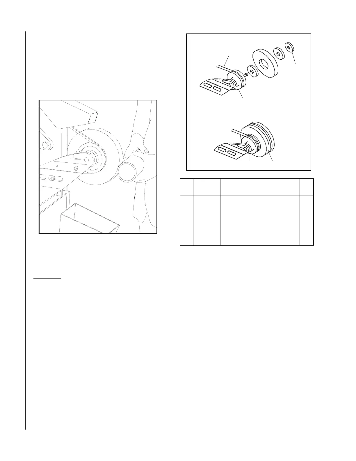
Figure 13: Hub and Wheel Assembly
4
1
V-Belt
Collar
Hub Shaft
Ref. Part
No. Number Description Qty.
1 5054920 Hub and Wheel Assembly 1
(Includes Hub Shaft, V-Belt,
Collar, and Special Wrench)
2 5045141 Polishing Wheel 1
3 5058071 Spacer Plate 2
4 5044620 Buffer Pad 1
Hub and Wheel Assembly
Refer to Figures 12 and 13. The hub and wheel
assembly Small Diameter Contact Wheels
can be used to adapt a number of other optional
attachments for use on the belt grinder. The assem-
bly consists of a pre-balanced hub shaft, collar, and
V-belt and a special wrench to enable quick change
of the optional attachments.
Install the hub and wheel assembly as follows:
WARNING: DISCONNECT ELECTRICAL
POWER TO THE MACHINE BEFORE INSTALL-
ING THE HUB AND WHEEL ASSEMBLY.
1. Lower tension lever to release belt tension.
2. Loosen clamping screw and remove platen
or contact wheel.
3. Remove work rest.
3. Insert the shaft of the hub in head casting.
Tighten the clamping screw.
4. Install the V-belt around the idler wheel,
drive wheel, and wheel of hub and wheel
assembly.
5. Raise tension lever to tighten belt.
6. Install polishing wheel or buffing pad as
follows:
A. Install one spacer plate on threaded
shaft.
B. Install polishing wheel or buffing pad.
C. Install second spacer plate and collar.
D. Tighten collar using special wrench.
Figure 12: Polishing with
Hub and Wheel Assembly
 Loading...