Maintenance3303−3/A1
Winterthur Gas & Diesel Ltd.
2/ 8
6) If necessary, put oil on the two bolts (7,
Fig. 2)
7) Install the two holders (94333) with the
four bolts (7) to the piston rod foot.
8) Torque the four bolts (7) to 200 Nm.
9) Tighten the bolts (6).
10) Use the turning gear to turn crank to
BDC. The connecting rod moves down
away from the piston rod foot.
11) Lock the turning gear to prevent
movement of the crankshaft.
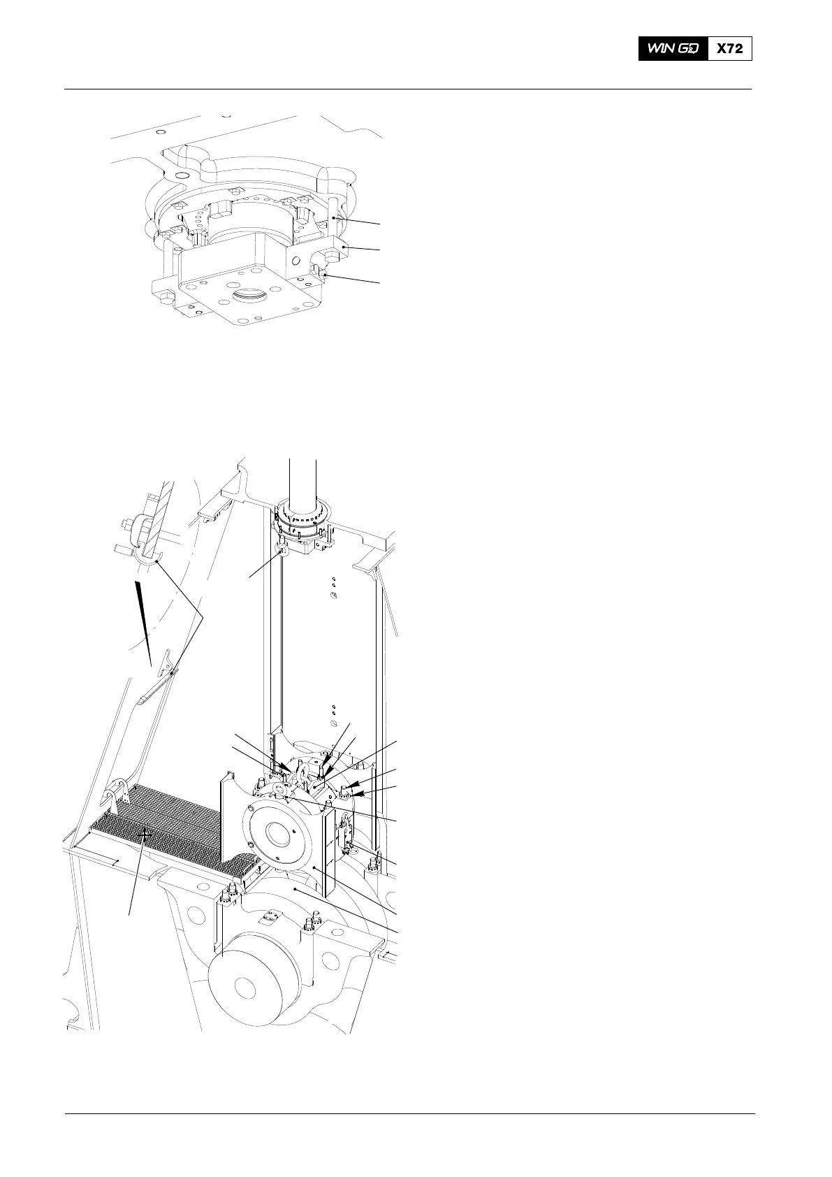
2. Preparation
1) Install the platform (94143, Fig. 3).
2) Install an eye bolt (94045-M48) near
the gland box.
3) Install an eye bolt (94045-M48) on the
guide shoe below the eye bolt near the
gland box.
4) Install the protection tool (94117B) on
top of column opening.
5) Use the pre-tensioning jack (94315) to
apply tension to the elastic stud (8) of
the connecting rod, refer to 9403−4.
6) Remove the four round nuts (9).
7) Put the lifting tool (94324) on to the
elastic studs (5).
8) Attach the round nuts (3) to the elastic
studs (5).
9) Tighten the round nuts with the round
bar (94005).
10) Install the stop plate (94335) to the
bearing cover (9).
11) Install the lifting tool (94337) to each
side of the connecting rod.
12) Torque the four bolts of the lifting tool
(94337) to 150 Nm.
13) Disconnect the toggle lever (10, Fig. 4)
from the connecting rod.
2015
Top End Bearing − Removal, Inspection Installation
94333
6
7
WCH02435
Fig. 2
Fig. 3
EXHAUST SIDE
94117B
WCH02433
94143
94324
94337
94335
94045-M48
3
2
1
94045-M48
5
8
9
15

 Loading...


