Maintenance3303−4/A1
Winterthur Gas & Diesel Ltd.
8/ 9
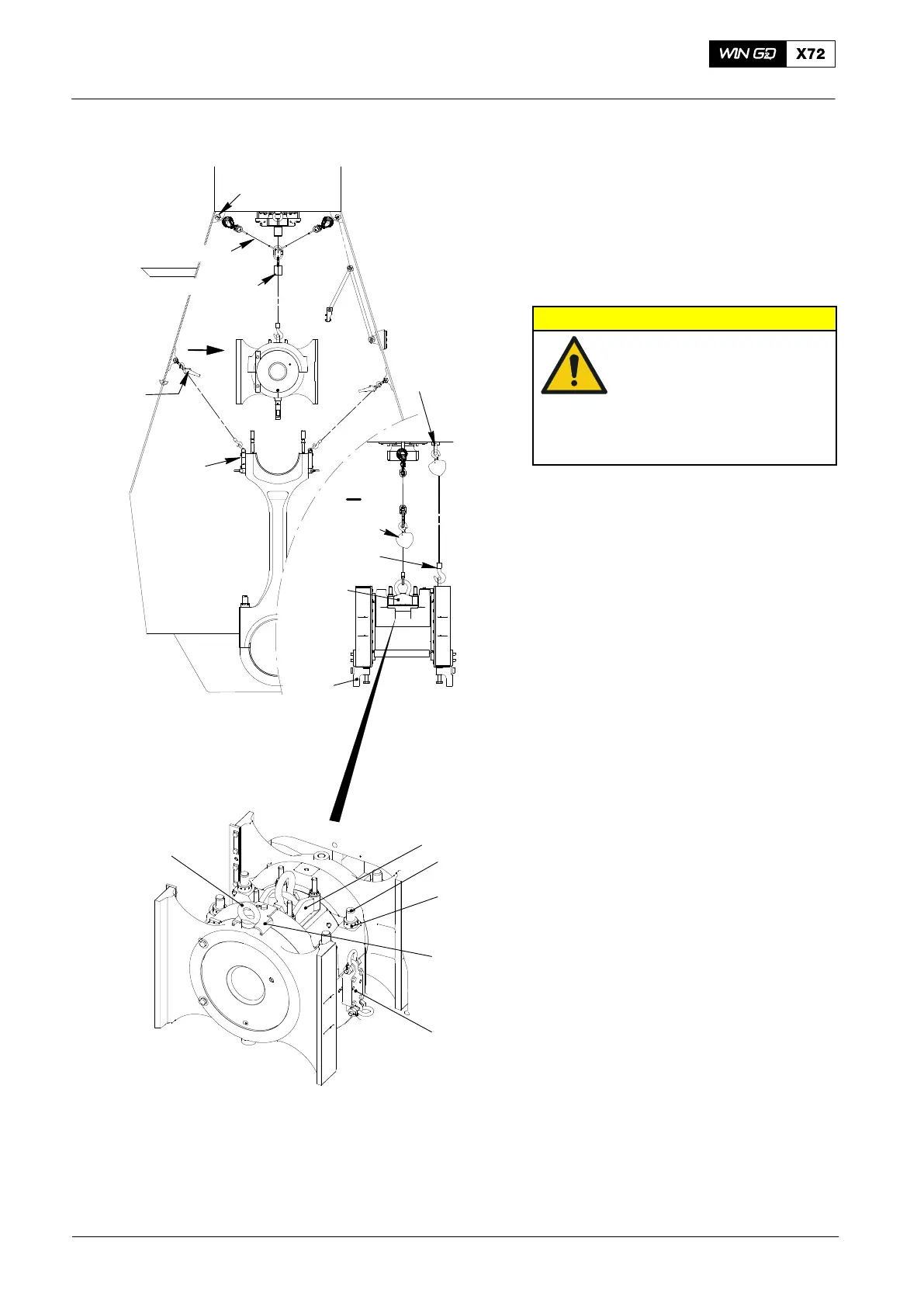
24) Use the turning gear and the manual
ratchets (H1 and H2, Fig. 13) to move
the connecting rod (1) and crankshaft
(2) clockwise into the position shown.
25) Make sure that there is tension on the
chain block (94016−017).
26) Remove the two supports (94332).
CAUTION
Damage Hazard: During
step 27), make sure that
the elastic studs are
aligned with the related
holes in the crosshead.
This will prevent damage
to equipment.
27) Operate the chain block (94016−017)
to lower the crosshead on to the
connecting rod (1).
28) Attach the four round nuts (6) to the
elastic studs (3).
29) Remove the chain block (94016−017).
30) Remove the tool (94324).
31) Remove the manual ratchets (H1, H2)
from the lifting tool (94337).
32) Remove the lifting tool (94324).
33) Remove the eye bolt (94045−M36).
34) Remove the stop plate (94355).
35) Remove the manual ratchets (H1, H2)
from the lifting tools (94337).
2015
Removal and Installation
Fig. 13
94337
94018C
94019B
94016-017
I
I
94016-17
94017-21
94322
94324
94045-M48
H2
H1
(H3)
(H4)
WCH02433
6
94324
3
94045-M36
WCH02433
94335
94337

 Loading...


