Maintenance3303−5/A1
Winterthur Gas & Diesel Ltd.
2/ 4
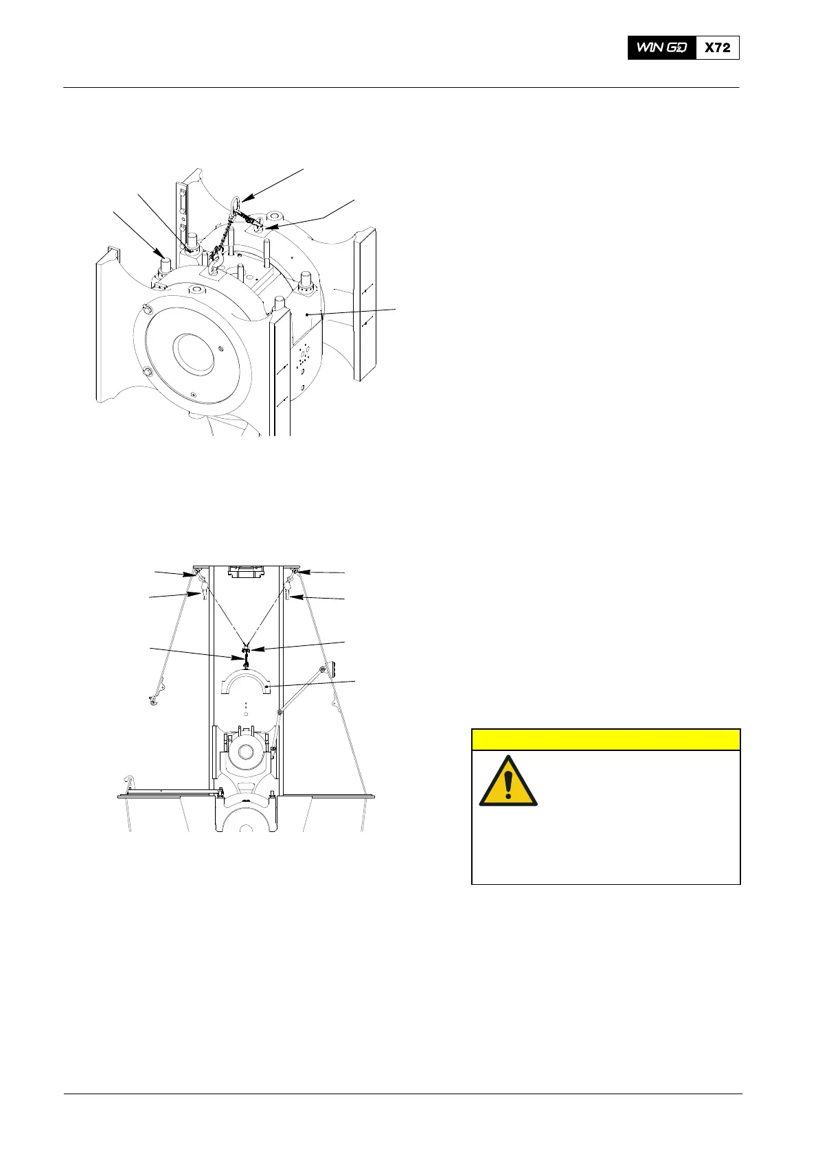
2. Removal
1) Use the pre-tensioning jack (94315) to
loosen the four round nuts (3, Fig. 2),
refer to 9403−4.
2) Remove the four round nuts (3) from
the elastic bolts (2).
3) Attach the two eye bolts (94045-M20)
to the bearing cover (1).
4) Attach the chain (94019C) to the two
eye bolts (94045-M20).
5) Attach the two shackles (94018C,
Fig. 3) to the strong-points on the
frame.
6) Attach the two manual ratchets
(94016−025) to the shackles (94018C).
7) Attach the two manual ratchets
(94016−025) to the shackle (94018B).
Make sure that the chain lengths of the
manual ratchets are equal.
8) Attach the chain (94019C) to the
shackle (94018B).
CAUTION
Damage Hazard: Before
you operate the manual
ratchets, make sure that
the chain is vertically
aligned with the center of
the bearing cover. This will
prevent damage to the
elastic bolts.
9) Operate the two manual ratchets
(94016−025) to carefully lift the bearing
cover (1).
2015
Top End Bearing Cover − Removal, Inspection and Installation
Fig. 2
WCH02662
94019C
94045−M20
2
1
3
Fig. 3
WCH02662
94016−025
94016−025
94018C94018C
1
94018B
94019C

 Loading...


