Maintenance
3326−2/A1
Winterthur Gas & Diesel Ltd.
3/ 10
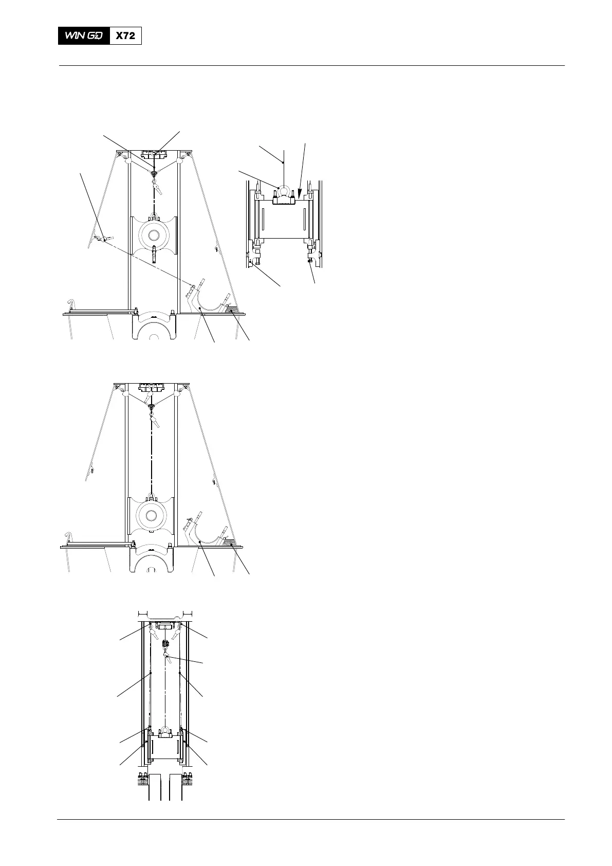
10) Use the manual ratchet (94016−017) to
lift the crosshead approximately
160 mm above the center of the pin
hole (3, Fig. 1 view II) and Fig 2).
Note: The two supports (94322) hold the
weight of the crosshead while you
move the connecting rod (6).
11) Attach the two supports (94322) to the
guide way as shown in Fig. 2).
12) Tighten the two set screws (5).
13) Put a wooden block (8) in position as
shown.
Note: During the step 14), slowly move
the connecting rod to the exhaust
side.
14) On the fuel side, gradually loosen the
manual ratchet. At the same time, keep
tension on the chain of the manual
ratchet on the exhaust side.
15) Continue with step 14) until the
connecting rod (6) touches the wooden
block (8).
16) Loosen the two set screws (5).
17) Lift the crosshead a small distance.
18) Remove the two supports (94322).
19) Remove the manual
ratchets (94016−011).
20) Lower the crosshead to the same
height as the column door frame (see
Fig. 3).
21) Attach the manual ratchets
(94016−009, Fig. 4) to the eye
bolts (94045−M48) on the guide
shoes (4) and (10).
22) Apply a light tension to the chains of
the manual ratchets (94016−009).
Make sure that the primary load stays
on the chain of the manual
ratchet (94016−017, see Fig. 4).
2015
Crosshead Pin − Removal / Installation / Clearance Checks
5
6
94322
94045−M48
94016−009
94045−M48
Turned
through
90°
FUEL SIDE
8
94016−011
94016−00994016−009
6
8
10
4
94045−M48
94016−017
94016−017
WCH02437
WCH02437
WCH02437
94045−M48
94045−M48
94045−M48
Fig. 2
Fig. 3
Fig. 4

 Loading...


