Maintenance5581−1/A1
Winterthur Gas & Diesel Ltd.
2/ 6
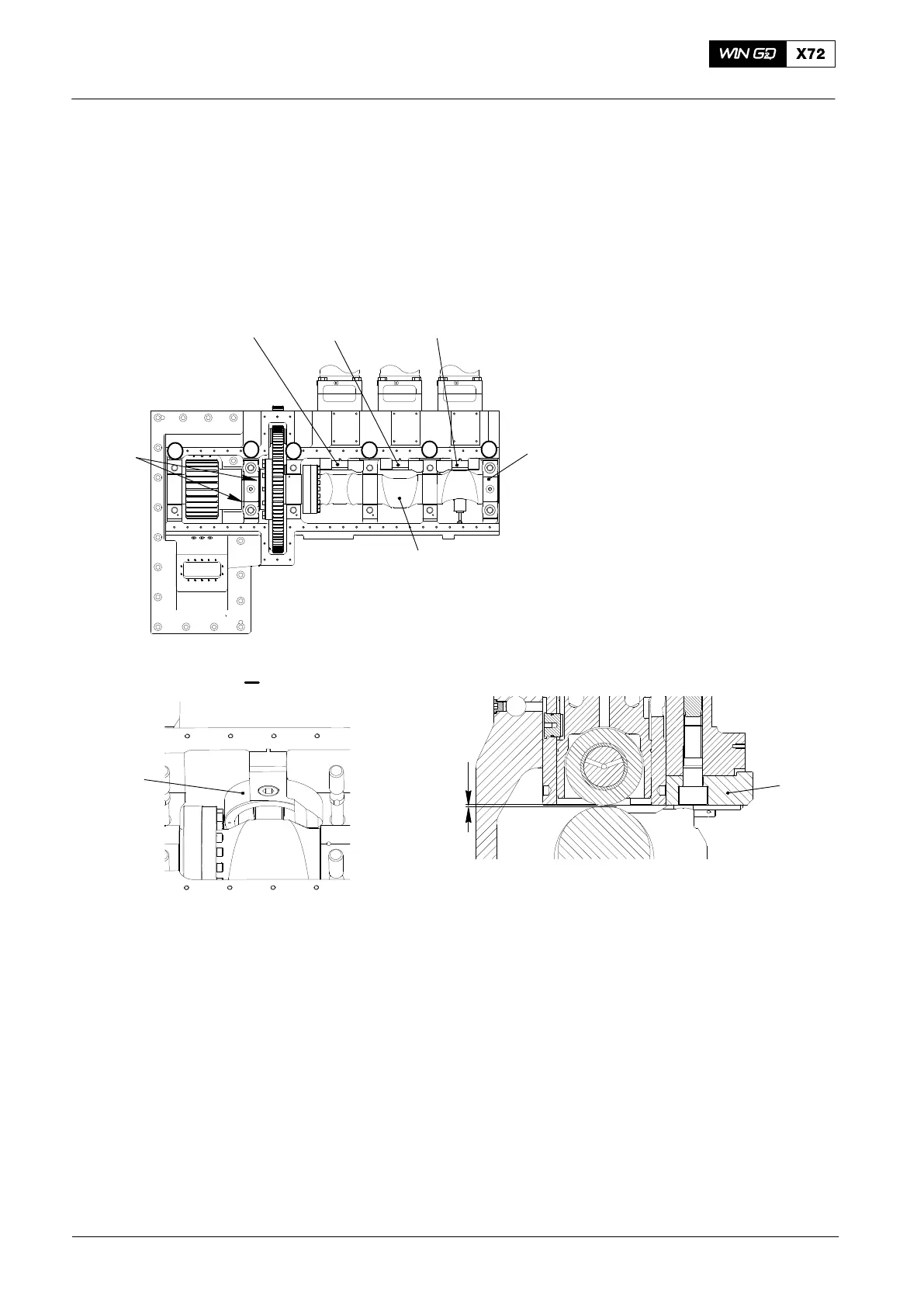
3) Make sure that the bearing covers at positions No. 3, No 4 and No. 5 Fig. 2 and
the housing (1), have marks to identify them as a set.
Note: The bearing at position No. 2 has the two thrust bearing ring halves (3).
4) Install the holders (94566B and 94566C) to lift up the rollers and guide pistons of
the fuel pumps.
94566C
1
2
I
94566B
WCH02383
94566
94566
2 mm
94566B
94566B
WCH02385
WCH02385
3
4
652
1
Fig. 2
3
2015
Camshaft and Bearing Shells − Removal and Installation

 Loading...


