Maintenance9223−1/A1
Winterthur Gas & Diesel Ltd.
2/ 3
2. Procedures
2.1 Proximity Sensors (ST5131−34C) − Replace
WARNING
Injury Hazard: Before you operate the turning gear, make sure
that no personnel are near the flywheel, or in the engine.
1) Stop the engine.
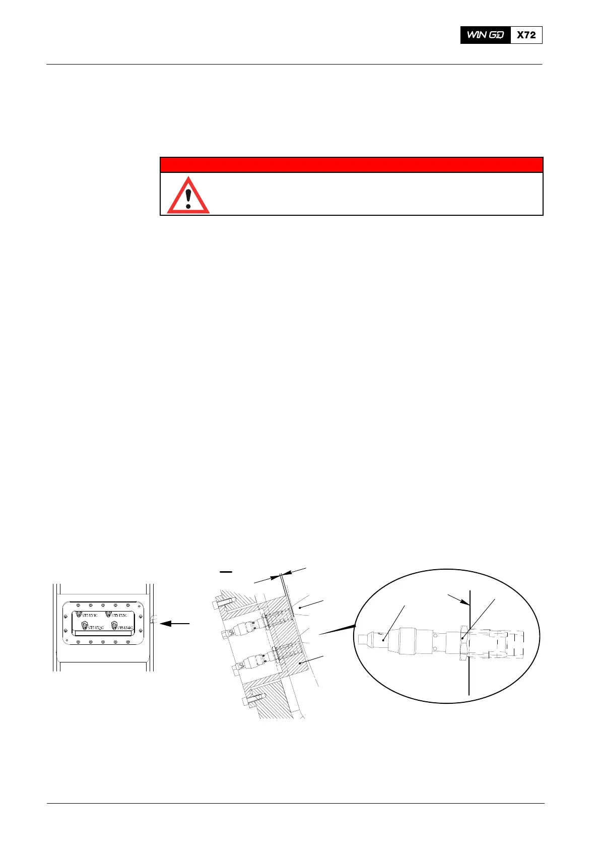
2) Operate the turning gear to get a tooth (1, Fig. 2) of the intermediate wheel
opposite the applicable proximity sensor (2).
3) Put a mark on the applicable cable to identify its position.
4) Disconnect the applicable electrical connection from the proximity sensor (2).
5) Loosen the locknut (4).
6) Remove the proximity sensor (2) from the holder (3).
7) Attach the new proximity sensor (2) to the holder (3).
8) Turn the proximity sensor (2) fully down until the tip of the proximity sensor (2)
touches the holder (3).
Note: During installation/commissioning the clearance between the flywheel
tooth (1) and the holder (3) is set to 2.0 mm.
Note: The wall thickness of the holder (3) is 1.5 mm.
9) Loosen the proximity sensor (2) a half turn to get a clearance of 4.0 mm between
the flywheel tooth (1) and the bottom face of the proximity sensor (2).
10) Carefully tighten the locknut (4) with your fingers.
11) Connect the electrical connection to the proximity sensor (2). Refer to the mark
made before to identify the correct cable.
3
2 mm
Fig. 2
I
I
4
3
2
WCH03215
1
Crank Angle Sensor Unit: Proximity Sensor − Replace
2016−11

 Loading...


