Maintenance
9223−1/A1
Winterthur Gas & Diesel Ltd.
3/ 3
2.2 Proximity Sensors (ZS5123C−24C) − Replace
WARNING
Injury Hazard: Before you operate the turning gear, make sure
that no personnel are near the flywheel, or in the engine.
1) Stop the engine.
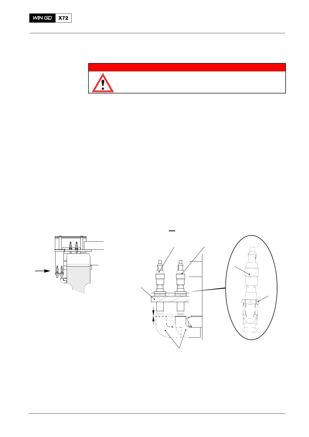
2) Operate the turning gear to get the applicable crank angle mark (2, Fig. 2) on the
flywheel wheel opposite the unserviceable proximity sensor.
3) Put a mark on the applicable cable to identify its position.
4) Loosen the locknut (1).
5) Remove the proximity sensor (4) from the holder (3).
6) Attach the new proximity sensor to the holder (3).
7) Make sure that the proximity sensor (4) touches the applicable crank angle
mark (2).
8) Loosen the proximity sensor (4) until you get a clearance of 4.0 mm between the
crank angle mark and the bottom face of the proximity sensor.
9) Carefully tighten the locknut (1) with your fingers.
10) Connect the electrical connection to the proximity sensor (4). Refer to the mark
made before to identify the correct connection.
ZS5123C
ZS5124C
Fig. 3
WCH03215
4.0 mm
2
3
4
I
I
1
For the function of the Crank Angle Sensor Unit, read the data in 4002.1
paragraph 4.6.
For the Inspection and Overhaul Intervals refer to Maintenance Schedule 0380−1,
Crank Angle Sensor Unit.
Crank Angle Sensor Unit: Proximity Sensor − Replace
2015

 Loading...


