10
© 2006 Wohler Technologies Inc. ALL rights reserved
AMP1A/-2S/-LP/-LP2S User Manual, P/N 821526, Rev-D
2
3
4
5
6
7
8
1
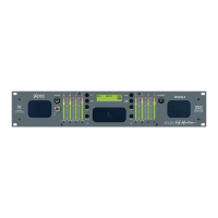
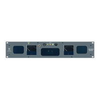
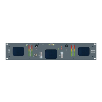
Please refer to Figure-2a on the following page to familiarize yourself with the front panel features of the AMP1A Series units
covered by this manual. The following sections describe these functions and are referenced, by number, to Figure-2a.
Section 2: Operation
Front Panel Features
Speakers
The AMP1A Series internal speaker system is comprised of two mid-range tweeter speakers (left and right) and two woofer
speakers (left and right). The two mid-range speakers reproduce, in stereo, only the mid and high frequencies, while the two
woofer speakers monorally reproduce the low frequencies. See page 14 for more information about the speaker configuration.
Volume Control
This controls the loudness of the audio reproduced by the internal speakers or connected headphone. Clock-wise rotation of this
control increases the loudness of the monitored audio.
Headphone Output
This jack accepts a standard 1/4” phone type stereo plug. Select the headphone audio sources as you would for the internal
speakers. When you plug in headphones, the internal speakers will mute.
Power Indication LED
This LED glows GREEN to indicate the unit is connected to operational mains power.
Balance Control
This pans the volume balance between the left and right speakers. See page 14 for balance characteristics.
Source Select Switch
(AMP1A-2S and AMP1A-LP2S only)
On the -2S models, this switch selects either the SOURCE 1 or SOURCE 2 inputs (Items E and F, page 12) for monitoring.
Audio Level Meters
(AMP1A-LP and AMP1A-LP2S Only)
Audio levels are visually displayed via these two 10-segment, tri-color (red, amber, green) LED bargraph display level meters.
Bargraph 1 monitors Channel A (left) while Bargraph 2 monitors Channel B (right). These meters are able to simultaneously
display signal levels using both PPM and VU standards. Alternate display modes are user selectable via a DIP switch module
accessible through the top cover. See page 17 for specifications and settings of these meters.
Phase Indication LEDs
(AMP1A-LP and AMP1A-LP2S Only)
These three LEDs indicate the instantaneous and average phase (polarity) conditions between the source(s) assigned to
the left speaker channel and the source(s) assigned to the right speaker channel. The larger LED labeled AVG indicates
the average phase condition between the left and right speaker channels. The two smaller LEDs labeled
ΦΦ
ΦΦ
Φ+ and
ΦΦ
ΦΦ
Φ-
indicate the instantaneous phase relationships. Indication is as follows:
• The upper
ΦΦ
ΦΦ
Φ+ LED glows (or blinks) GREEN for in-phase signals.
• The lower
ΦΦ
ΦΦ
Φ- LED glows (or blinks) AMBER for out-of-phase signals.
• The large center AVG LED indicates the average phase condition by glowing GREEN for in-phase signals, or RED
for out-of-phase signals.
In general, observing the AVG LED alone is sufficient for proper phase monitoring. While it is normal for stereo signals to
contain some intermittant instantaneous out-of-phase and in-phase conditions (
ΦΦ
ΦΦ
Φ+ and
ΦΦ
ΦΦ
Φ- LEDs), a steady RED glow of
the AVG LED indicates an out-of-phase alarm condition.