12
© 2006 Wohler Technologies Inc. ALL rights reserved
AMP1A/-2S/-LP/-LP2S User Manual, P/N 821526, Rev-D
A
B
C
D
E
F
G
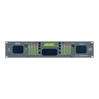
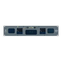
Please refer to Figure-2b on the following page to familiarize yourself with the rear panel features of the AMP1A Series units covered by
this manual. The following sections describe these features and are referenced, by letter, to Figure-2b.
Power Connector
Attach a standard IEC-320 power cord between this connector and mains power (100 - 250VAC, 50/60 Hz). The front
panel Power LED (Item 4) will glow GREEN to indicate operating voltages are present.
Balanced Input Connectors
(AMP1A and AMP1A-LP Only)
These two balanced (200K Ω) XLR connectors (left and right) accept standard analog audio signals. Pinout information
for connectors is shown at bottom of this page.
Loop-Through Output Connectors
(AMP1A and AMP1A-LP Only)
These two XLR connectors output a balanced (200K Ω) analog audio loop-through of the signals entering the balanced
inputs (Item B). Pinout information for connectors is shown at bottom of this page.
Unbalanced Input Connectors
(AMP1A and AMP1A-LP Only)
These two unbalanced (40K Ω) RCA Phono connectors accept standard analog audio signals. Pinout information are
shown below.
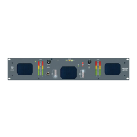
Source 1 Input Connectors
(AMP1A-2S and AMP1A-LP2S Only)
These two balanced (200K Ω) XLR connectors accept standard analog audio signals. Signals entering these connectors
are selected for monitoring by setting the Source Select Switch on the front panel (Item 6) to 1. Pinout information for
connectors is shown at bottom of this page.
Source 2 Input Connectors
(AMP1A-2S and AMP1A-LP2S Only)
These two balanced (200K Ω) XLR connectors accept standard analog audio signals. Signals entering these connectors
are selected for monitoring by setting the Source Select Switch on the front panel (Item 6) to 2. Pinout information for
connectors is shown at bottom of this page.
Selected Output Connectors
(AMP1A-2S and AMP1A-LP2S Only)
These two 3-pin male XLR connectors are analog outputs of the audio source (1 or 2) as selected by the Source Select
Switch on the front panel (Item 6). The output is not affected by the volume/balance controls or headphone mute
feature. Pinout information for connectors is shown below.
Rear Panel Features
Section 2: Operation
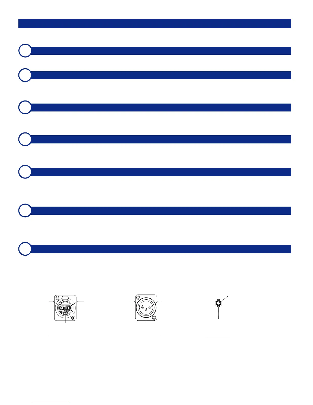
High (+)
Low (-)
Gnd
(Shield)
Pin-1 Pin-2
Pin-3
Pin-1
Gnd
(Shield)
Pin-2
High (+)
Pin-3
Low (-)
Female XLR Pinout Male XLR Pinout
Center
(Hot)
Sleeve
(Shield)
Female RCA
Phono Pinout
 Loading...