Sawmill Assembly
Saw Carriage Assembly
3
3-5 15doc092319 Sawmill Assembly
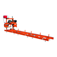
3.5 Saw Carriage Assembly
The saw carriage is equipped with two lock pins at the bottom of the mast near the track rollers.
These pins can be adjusted to three different positions:
1. Operation position. The pins catch the bottom of the track rail, preventing the saw head from
tilting and disengaging the bed frame.
NOTE: The pins are designed so if they are inadvertently left in the assembly
position, they will move to the operation position when the carriage is moved.
2. Travel position. Secures the saw head to the bed frame during travel. Rotate the pin at the end
of the sawmill so it is clear of the pin bracket. Be sure the pin engages the hole in the bed frame
tube. The other pin should remain in the operation position to prevent the saw head from tilting.
See Figure 3-6.
IMPORTANT! Before beginning saw carriage assembly, make sure both lock
pins are in the assembly/disassembly position (lock pins seated in upper
notches of pin rest brackets).
3. To reposition pin, pull pin outward, rotate as desired, and release into proper position.
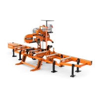
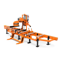
4. Position the saw head carriage at the end of the bed frame assembly.
1). Carefully slide the saw head carriage rollers onto the bed frame track.
2). Keep the carriage square to the bed to avoid putting the track rollers in a bind.
5. Place both carriage lock pins in the operation position to secure carriage onto bed frame assem-
bly.
FIG. 3-6
DETAIL
Pull, rotate and
release pin to
appropriate position
(See Detail)
 Loading...