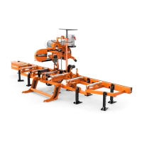
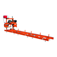
Sawmill Operation
4
Sawmill Operation LX25 12/21/22 4-3
3. Measure between the back edge of the blade and the tool at the end closest to the inner blade guide ("B").
4. Measure between the back edge of the blade
and the other end of the tool ("A").
The roller should be tilted slightly to the left (’A’ 1/8"
[3 mm] less than ’B’ ±1/8" [3 mm]).
5. Loosen the jam nuts on the horizontal tilt adjust-
ment screws. See FIG. 4-7.
1). To tilt the roller left, loosen the right
screw and tighten left screw. Reverse to tilt
right. Tighten the jam nuts and recheck the
tilt of the blade.
INNER BLADE GUIDE
6. Repeat the above steps for the inner blade guide
roller assembly.
NOTE: Once the blade guides have been adjusted,
any cutting variances are most likely caused by the blade.
Blade guides
Check the ceramic blade guides for the proper setting.
The two round ceramic guides should hover over and under the blade
between 0.0075-0.010 inches (0.2 - 0.25mm) -- use the provided 0.0075"
shim (p/n 035248) as a gauge.
The adjustment bolts for the top and bottom guides face the foot of the
sawmill. (See FIG. 4-9 and FIG. 4-10.)
NOTE: Before setting or adjusting the ceramic
blade guides the blade must be at the correct
tension and tracked on the band wheels.
A square ceramic guide lies in the middle of the blade guide assembly. This guide should be positioned approximately 1/8 inch
from blade back. Use the set screw on the side of the blade guide assembly to hold the position of the square guide. (See FIG.
4-10 .)
to tilt roller left; Adjust
screws left to tilt roller
right
Horizontal Tilt
Adjustment Screws
FIG. 4-7
Blade flush to
3mm(1/8") overhang
here, both wheels
FIG. 4-8
FIG. 4-9

 Loading...