24 Dealer Service
MAN0999 (12/4/2012)
release link and free park brake release rod. (If
drive wheel rotates with park brake engaged, there
may be internal hydrostatic problems. Contact
authorized Hydro-Gear
®
dealer).
3.
Check to see if there is spring tension on hydrostat
brake arm. Hydrostat brake arm should be roughly
horizontal with park brake engaged. Tension
spring to 1/8" past initial tension. Repeat 1.
4.
Loosen lock nut on top of park brake release link.
Reinstall screw and park brake release link.
5.
With control handles in the outer park position,
park brake release link should be at top of slot in
control rod. Adjust rod until park brake release link
is at top of slot with no pressure. Tighten lock nut.
Repeat 1.
6.
Move control arm to neutral drive position, check to
see if drive wheel rotates. Park brake release arm
should be pushing down on hydrostat brake arm,
releasing the parking brake.
7.
Confirm free movement of control arm, park brake
release rod and parking brake spring.
8.
Repeat for opposite side.
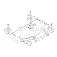
CLUTCH REPAIR
Figure 11
. Clutch Assembly
Remove Components
1.
Position unit on level ground and set control
handles in park (pivoted outward), stop engine and
remove key.
2.
Loosen PTO idler arm spring and remove belt.
3.
Disconnect electrical wire harness from clutch (1).
4.
Remove screw from end of crank shaft.
5.
Remove clutch from crank shaft. Be sure to
capture spacer between clutch (1) and drive pulley
(2). Drive pulley (2) is held on by drive belt. If no
drive belt is installed at this point, drive pulley (2)
and top spacer (3) will also come off of crankshaft.
Install Clutch
1.
Install spacer (3), drive pulley (2) if previously
removed.
2.
Install spacer (3) between drive pulley (2) and
clutch (1).
3.
Align key on clutch (1) with keyway on crankshaft.
4.
Align anti rotation rod with closed slot of clutch (1).
5.
Install clutch (1) on crankshaft.
6.
Insure that clutch (1) engages anti rotation rod.
7.
Place drop of Loctite 242 (Blue) on threads of
screw.
8.
Install screw and torque to 55-60 FT-LB.
9.
Reinstall belt and retighten idler arm spring to
proper belt tension.
10.
Attach electrical wiring harness. Insure wiring
harness is held out of the way of moving parts and
belts.
11.
Follow Clutch Burnishing instructions on page 20.
RETURN TO OPERATION
When you have completed service and maintenance
functions, read and comply with these safety mes-
sages before returning unit to operation.
Make sure all safety decals are installed.
Replace if damaged. (See Safety Decals section for
location.)
Make sure shields and guards are properly
installed and in good condition. Replace if damaged.
 Loading...