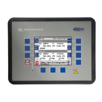
Manual 37128A GCP-20 Series - Genset Control
© Woodward Page 167/190
No. Content (words) Unit Comment
12
Control register 1 Bit 15 = 1 \
Bit 14 = 1 /
Internal
Bit 13 = 1
Internal
Bit 12 = 1
Internal
Bit 11 = 1 \
Bit 10 = 1 /
Execution of acknowledgment of a F2/F3
alarm
Bit 9 = 1 \
Bit 8 = 1 /
Execution of acknowledgment of a
F1-alarm
Bit 7 = 1 \
Bit 6 = 1 /
Internal
Bit 5 = 1 \
Bit 4 = 1 /
Internal
Bit 3 = 1 \
Bit 2 = 1 /
Internal
Bit 1 = 1
Internal
Bit 0 = 1
Internal
13
Reserve Internal
14
Internal fault 6 Bit 15 = 1 \
Bit 14 = 1 /
Pickup plausibility alarm
Bit 13 = 1 \
Bit 12 = 1 /
Unit activation malfunction
Bit 11 = 1
MCB switch malfunction
Bit 10 = 1
GCB switch malfunction
Bit 9 = 1
MCB synchronization time monitoring
Bit 8 = 1
GCB synchronization time monitoring
Bit 7 = 1
Internal
Bit 6 = 1
Internal
Bit 5 = 1
Internal
Bit 4 = 1
Internal
Bit 3 = 1
Range alarm analog input 4
Bit 2 = 1
Range alarm analog input 3
Bit 1 = 1
Range alarm analog input 2
Bit 0 = 1
Range alarm analog input 1
15
Phase-to-phase generator voltage V
23
V × 10
UGNEXPO
16
Phase-to-phase generator voltage V
31
V × 10
UGNEXPO
17
Generator star voltage V
1N
V × 10
UGNEXPO
18
Generator star voltage V
2N
V × 10
UGNEXPO
19
Genertor voltage Star V
3N
V × 10
UGNEXPO
 Loading...
