For Customer Care call: Toll Free 800-562-5625 or info@hamptonproducts.com
DOOR CLOSER
WC13/WC14 INSTALLATION INSTRUCTIONS
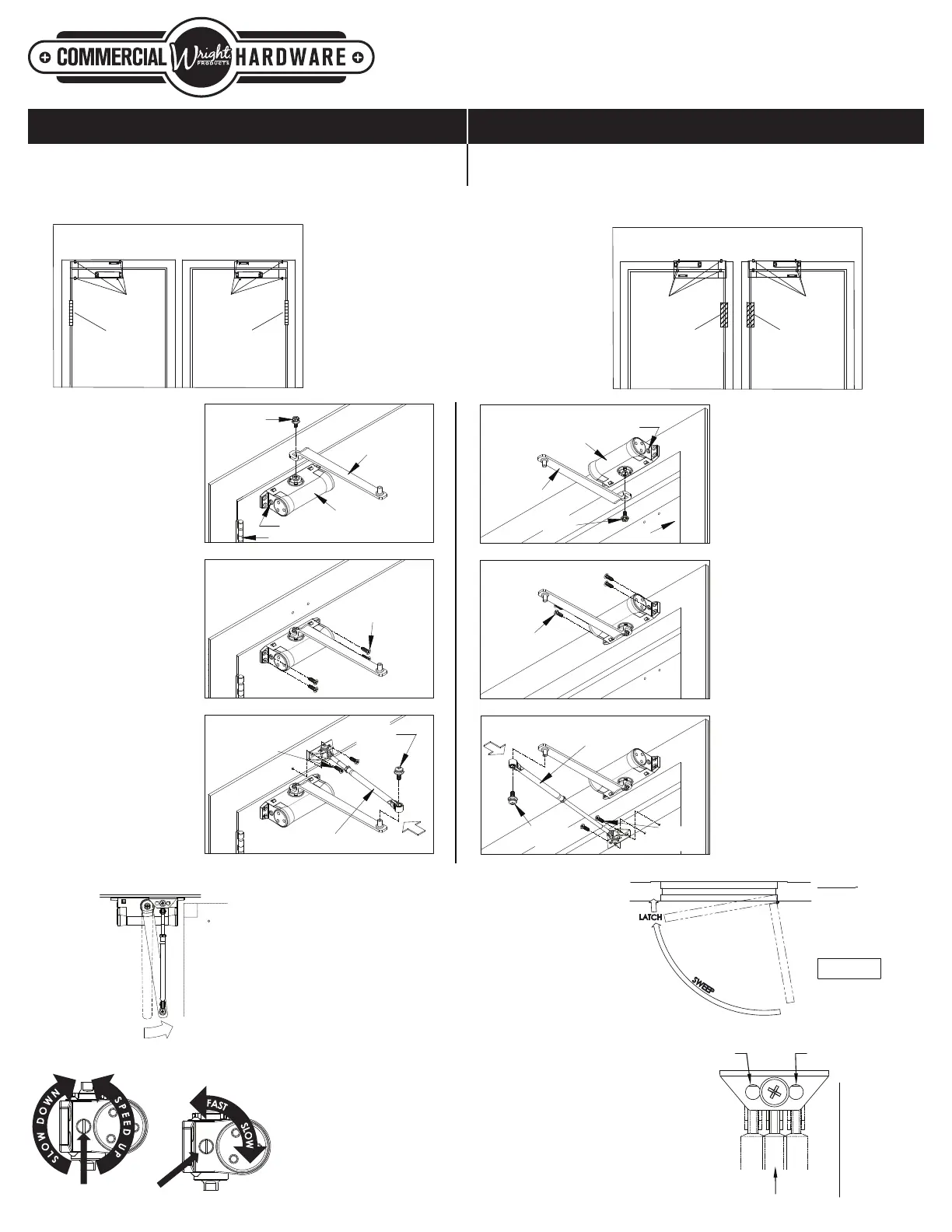
INWARD OPENING DOORS
OUTWARD OPENING DOORS
Cut out the right or left hand template marked “INWARD OPENING”. Tape the
template to the upper edge of the door on the hinge side, following template
instructions for desired degree opening.
The templates are in two parts. Cut out the right or left hand templates marked “OUTWARD
OPENING”. Tape the closer body and forearm shoe templates following the template instructions
for desired degree opening.
3B. MARKING HOLE LOCATION.
Use a hammer and punch to mark the center of each
screw
hole then remove the template.
3C. PREPARING SCREW START HOLES
NOTE: Numbers in parentheses ( ) indicate the item
number shown in Parts and Assembly Diagram on the
front of this sheet.
a. Wood Door
Soft Wood – use a 1/8” drill bit and drill four holes for the
closer body (1) and two holes for the forearm and shoe
assembly (3) 1-1/4” deep.
Hard Wood – use a 5/32” drill bit and drill four holes for the
closer body (1) and two holes for the forearm and shoe
assembly (3) 1-1/4” deep.
b. Aluminum or Steel Door
Use a drill with a 5/32" bit and drill four holes for the body
(1) and two holes for the forearm shoe (3) approximately
3/4" deep.
3D. ATTACHING MAIN
ARM TO BODY
NOTE: Speed adjustment
valve on closer body
must be positioned
towards the door hinge.
Place main arm onto the
BOTTOM spindle of the
closer body for an outward
opening door and attach
with hex screw, lock
washer and flat washer.
3E. ATTACHING BODY
Position closer body with
main arm attached over the
drilled holes on the jamb.
The spindle with main arm
attached must be on the
bottom. Fasten closer to
door using screws for either
wood or aluminum door
jambs.
3F. ATTACHING
FOREARM AND SHOE
ASSEMBLY
Position the forearm shoe
over holes on the door and
fasten using screws for
either wood or aluminum
doors.
3D. ATTACHING MAIN
ARM TO BODY
NOTE: Speed adjustment
valve on closer body
must be positioned
towards the door hinge.
Place main arm onto the
TOP spindle of the closer
body for an inward
opening door and attach
with hex screw, lock
washer and flat washer.
3E. ATTACHING BODY
Position closer body with
main arm attached over
the drilled holes on the
door. The spindle with
main arm attached must
be on the top. Fasten
closer to door using
screws for either wood or
aluminum doors.
3F. ATTACHING
FOREARM AND SHOE
ASSEMBLY
Position the forearm
shoe over holes on the
top door jamb and
fasten using screws for
either wood or aluminum
door jambs.
TAPE
HINGE
OPPOSITE
Right Hand Door
HINGE
TAPE
TAPE
HINGE
Left Hand Door
Right Hand Door
HINGE
OPPOSITE
TAPE
Left Hand Door
ATTENTION
:
ADJUST CLOSING SPEED
TIME TO BETWEN 4 & 6
SECONDS FROM 90°.
DOORS USED BY:
HANDICAPPED, ELDERLY
OR SMALL CHILDREN MAY
REQURE LONGER
CLOSING TIMES.
STANDARD
CLOSING
CYCLE
10°
CLOSING SPEED CONTROL
3G. CONNECTING MAIN ARM TO FOREARM
Adjust length of forearm to position the forearm at a right angle to
frame, when connected to main arm at the elbow. Use washer and
screw (4) provided to secure the pivot connection. Tighten forearm
locknut.
Important: When door is fully closed and the forearm is at a 90
degree angle to the door, this position creates pressure, which
forces the door closed.
4. SPEED ADJUSTMENT
Closer speed is factory set. If a different speed is desired, both
sweep and latch speed can be adjusted by a single screw
adjustment.
4A. SWEEP SPEED ADJUSTMENT
Turn speed adjustment screw clockwise (1 turn) for a slower speed
and counter clockwise (1 turn) for a faster speed. Do not exceed two
turns in either direction.
4B. LATCHING SPEED ADJUSTMENT
For fastest latching speed, the slot in the adjustment screw is parallel
to the door. For a slower latching speed, the slot in the adjustment
screw is perpendicular to the door.
5. ATTACH COVER
Slide cover (8) onto body (1).
ADJUSTING LENGTH OF FOREARM
(template #1)
(template #2)
(template #3) (template #4)
CAUTION: DO NOT BACK
VALVES OUT OF CLOSER
OR LEAK WILL RESULT.
3G
PRELOAD
MAIN ARM
90
LATCH SPEED
ADJUSTMENT
SWEEP SPEED
ADJUSTMENT
ADJUSTING
SCREW
6. INITIAL OPENING POWER ADJUSTMENT
Adjusting foot for opening power (see illustration on right)
4A
4B
MOVE FOOT PIVOT TO HOLE AS ILLUSTRATED
LESS POWER
MORE POWER
STANDARD POSITION
HINGE EDGE OF DOOR
ADJUSTING FOOT FOR INITIAL OPENING POWER
ADJUSTING SCREW
ADJUSTING SCREW
BODY
BODY
MAIN ARM
MAIN ARM
MAIN ARM
SCREW
HINGE
MAIN ARM
SCREW
WOOD OR
SELF-TAPPING
SCREWS
WOOD OR
SELF-TAPPING
SCREWS
WOOD OR
SELF-TAPPING
SCREWS
FOREARM
FOREARM
CONNECTING
SCREW
WOOD OR
SELF-TAPPING
SCREWS
FOREARM
CONNECTING
SCREW
FOREARM
HINGE
3D
3D
3E
3E
3F
3F
 Loading...