CRD-XP
Product information
Page 4 of 4 Subject to technical changes CRD-XP_V3.9.8_PI_2020-02_EN
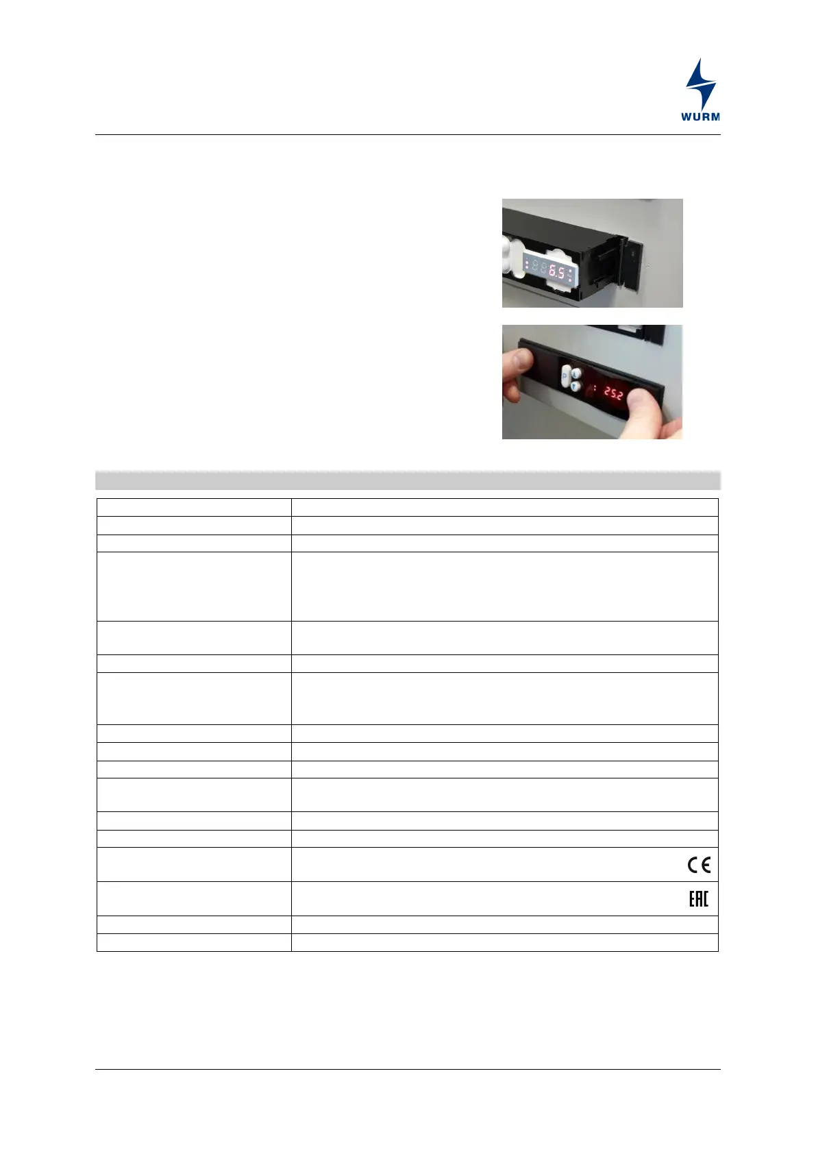
CRD-XP installation
The CRD-XP controller is
installed in the refrigeration unit or control cabinet door.
1. Attach the frame clips on the left and right of the installation
frame wall.
2. C
onnect the controller wires.
3. P
lace the controller on the guide rails of the frame clips
and
pus
h it into the installation frame.
4. Align the sealing frame in the back of the front panel and
press in firmly.
5. P
lace the front panel with sealing frame on the controller.
6. P
ress the front panel in until it is heard to engage.
Technical data
Through transformer TR9-9-4
2 x floating (multifunction inputs)
3 x TRK277/7 PLUS, DGF, T20015, K243
Output relay
1 x fan, normally open contact, 230V~, 3(2)A
1 x cooling, normally open contact, 230V~, 3(2)A
1 x defrost, normally open contact, 230V~, 3(2)A
The total current of these output relays must not exceed 12A.
Communication
3-wire CAN bus interface with integrated power supply, galvanically
isolated, service socket
4-wire RS485 interface with power supply, galvanically isolated
Min. load resistance
1 x 0…10V=, non-floating, short-circuit proof
2.5kΩ / 10kΩ
(W x H x D) 158 x 32 x 75mm
In the installation cut-out with holding clips and sealing frame
(120 x 28mm)
Operation: 0...+55°C, storage: -25…+70°C
CE conformity
− 2014/30/EU (EMC Directive)
− 2014/35/EU (Low Voltage Directive)
EAC conformity
−
 Loading...