This document describes the WUZHI WZ5020L 1kW DC 50V 20A Buck Converter, a digital control power supply module.
Function Description
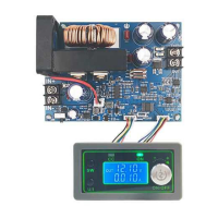
The WZ5020L is a step-down (buck) converter designed to regulate voltage and current. It features a digital display and control panel for setting output voltage, current, and various protection parameters. The module includes a main board with power components, a cooling fan, and a separate display and setting panel connected via key connections. It provides output voltage, current, and power monitoring, as well as input voltage and output capacity/time tracking.
Important Technical Specifications
The WZ5020L (model WZ5005L in the parameters table) offers a wide range of operation and precise control:
- Input Voltage Range: 6-55.00V
- Output Voltage Range: 0-50.00V
- Output Current Range: 0-20.00A
- Output Power Range: 0-1000W
- Input Voltage Resolution: 0.01V
- Output Voltage Resolution: 0.01V
- Output Current Resolution: 0.01A
- Input Voltage Accuracy: ±(1%+5)
- Output Voltage Accuracy: ±(0.3%+5)
- Output Current Accuracy: ±(0.5%+5)
- Typical Output Ripple: 150mV Peak value
- Normal Operating Temperature Range: -10°C to 40°C
- Capacity Measurement Range: 0-999.9AH
- Statistical Error of Capacity Energy: ±2%
- Statistical Time Range: 0-100 hours
- Depressurization Mode: Differential pressure >0.05%+1V
- Soft Start: Yes
- Product Size:
- Panel: 79mm (Long) x 43mm (Wide) x 42mm (High)
- Main Board: 106mm (Long) x 76mm (Wide) x 40mm (High)
- Weight:
- Nude: 200g
- Including packing: 242g
- Including lines: about 200g
Protection Mechanisms:
The device incorporates several protection features to ensure safe operation:
- Input Undervoltage Protection (LUP): Adjustable from 5.8V to 50V (default 5.8V).
- Output Overvoltage Protection (OUP): Adjustable from 0V to 51.00V (default 51V).
- Output Over-current Protection (OCP): Adjustable from 0V to 20.10A (default 20.10A).
- Timeout Protection (OHP): Adjustable from 0 to 100 hours (off by default).
- Over Capacity Protection (OAP): Adjustable from 0 to 999.9AH (off by default).
When a protection mechanism is triggered, the output automatically turns off, and the LCD displays a protection code. Pressing any key exits the protection interface.
Usage Features
The WZ5020L is controlled via a display and setting panel with three main controls: SW button, U/I button, and a Rotary Encoder.
Normal Interface Operations:
- SW Button (Short Press): Switches the display content below the screen between current (A), power (W), capacity (Ah), and time (h).
- SW Button (Long Press): Switches the uplink display on the screen between input voltage (IN) and output voltage (OUT).
- U/I Button (Short Press): Enters the interface for regulating voltage and constant current.
- U/I Button (Long Press): Enters the interface for setting parameters.
- Rotary Encoder (Short Press): Adjusts the parameter shift accordingly in setting interfaces.
- Rotary Encoder (Left/Right Rotation): Decreases/increases the corresponding bit of the adjustment parameter.
Setting Output Voltage:
- From the normal interface, press the U/I button to enter the voltage/current setting interface. A digit of the output voltage value will flash.
- Rotate the rotary encoder left/right to adjust the major and minor values.
- Short press the rotary encoder to select which bit of the output voltage to set.
- After setting, press the U/I button twice to return to the normal interface, or it will automatically return after 10 seconds of inactivity.
Setting Constant Current Value (Maximum Output Current):
- From the normal interface, press the U/I button to enter the voltage/current setting interface.
- Press the U/I button again to switch to setting the constant current value. A digit of the constant current value will flash.
- Rotate the rotary encoder left/right to adjust the major and minor values.
- Short press the rotary encoder to select which bit to set.
- After setting, press the U/I button to exit and return to the normal interface, or it will automatically return after 10 seconds of inactivity.
Setting Default Power-On State (Output ON/OFF):
- From the normal interface, long press the U/I button to enter the parameter setting interface.
- You will see "OPEN OFF" (output OFF by default) or "OPEN ON" (output ON by default).
- Long press the rotary encoder to switch between these two states.
- After setting, long press the U/I button to return to the normal interface.
Setting Protection Parameters (State and Threshold):
- From the normal interface, long press the U/I button to enter the parameter setting interface.
- Press the SW button repeatedly until the desired protection parameter appears (LUP, OUP, OCP, OAP, OHP).
- Short press the rotary encoder to select which bit to set for the protection parameter.
- Long press the rotary encoder to turn the protection parameter on or off (only timeout and supercapacity protection can be set to turn on/off; others are on by default).
- Rotate the encoder left/right to adjust the parameter values.
- After setting, long press the U/I button to return to the normal interface.
Maintenance Features
Calibration Voltage and Current:
- From the normal interface, long press the U/I button to enter the parameter setting interface.
- Press the SW key repeatedly until the interface with "zero" appears (e.g., "zero + out + a" symbol).
- Press and hold the rotary encoder to complete zero calibration.
- Continue pressing the SW button until a parameter interface with "CAL" appears.
- You will see interfaces for calibrating input voltage (CAL+IN+V), output voltage (CAL+OUT+V), and output current (CAL+OUT+A).
- Rotate the encoder left/right to adjust the parameter values.
- After adjustment, long press the rotary encoder to confirm. The parameter value will stop flashing.
- Long press the U/I button to return to the normal interface.
Calibration Notes:
- For accurate voltage calibration, the voltage must be above 12V.
- For accurate current calibration, the current must be above 1A.
General Cautions:
- Input Polarity: The input positive (IN+) and negative (IN-) must not be reversed.
- Short Circuit: The input negative (IN-) must not be short-circuited with the output negative (OUT-), as this can burn out the module.
- Power Supply: Ensure the input power supply's momentary power exceeds the required power of the output load.
- Step-Down Module: This is a step-down module; the input voltage must always be higher than the output voltage, with a certain margin. For full load output, the input voltage should be 55V.
- Heat Dissipation: When using the module at high power, significant heat will be generated. Pay attention to ventilation and heat dissipation to prevent scalding and ensure long-term operation.
- Undervoltage Protection: The module has input undervoltage protection (default 5.8V, adjustable). If the input voltage drops below this threshold, the output will disconnect. Be aware that voltage drop across input wires can occur with high input currents, so consider the actual voltage at the module's input terminals.